
1. Introduction
Vacuum pump sealing technology plays a decisive role in the performance, reliability, and service life of modern vacuum systems. Whether used in semiconductor fabrication, chemical processing, analytical instruments, or clean energy manufacturing, a well-designed sealing system is the foundation for maintaining pressure stability and process integrity.
Seals are not simply mechanical barriers. In vacuum applications, they must achieve extremely low leakage rates, withstand harsh chemical or thermal conditions, and remain stable over long operational cycles. Selecting the right sealing technology requires a holistic view of multiple engineering factors — including vacuum level, media properties, material compatibility, geometry, installation practices, and maintenance strategies.
This article provides a comprehensive, engineering-focused overview of vacuum pump sealing technology, structured to support technical personnel, equipment designers, and maintenance engineers. It covers:
- Vacuum and leakage fundamentals — how seals influence base pressure, outgassing behavior, and pump-down times.
- Classification of sealing methods — static and dynamic seal technologies, their principles, and typical use cases.
- Material selection — elastomers, plastics, metals, and coatings, with guidance on chemical and thermal compatibility.
- Seal selection framework — a systematic approach for choosing the right sealing solution based on duty conditions and lifecycle cost.
- Installation and maintenance best practices — from groove design and surface finish to monitoring and predictive maintenance.
- Sector-specific considerations — addressing the needs of industries such as semiconductor manufacturing, chemical processing, and biopharma.
- Modern trends and emerging technologies — including magnetic fluid seals, smart monitoring, and advanced coatings.
Throughout the article, practical engineering tools such as compatibility tables, decision trees, and case studies are provided to bridge theory and application. The goal is to help you:
- Understand how sealing technology impacts vacuum system performance.
- Select the right materials and designs for specific process requirements.
- Implement best practices in installation, operation, and maintenance.
- Adopt modern technologies to increase uptime and reduce lifecycle cost.
A robust sealing strategy is not just about preventing leaks — it is a cornerstone of process control, product quality, and operational efficiency.
2. Fundamentals of Vacuum & Leakage Metrics
Understanding how seals interact with a vacuum environment begins with a solid grasp of vacuum science and the mechanisms of leakage. Unlike pressure systems where fluid escape is visible and often abrupt, vacuum leaks can be microscopic, insidious, and highly consequential. Even a small imperfection in the sealing interface can compromise pump-down time, system stability, and process cleanliness.
2.1 Vacuum Ranges and Their Implications for Sealing
Vacuum levels are typically categorized according to the absolute pressure in the system. Each range imposes different sealing demands in terms of materials, outgassing tolerance, and allowable leakage rates:
| Vacuum Range | Absolute Pressure (Pa) | Typical Applications | Common Seal Types |
|---|---|---|---|
| Rough Vacuum | 10⁵ – 10² Pa | Pneumatic conveying, drying, vacuum packaging | Elastomer O-rings, gaskets, oil seals, packing seals |
| High Vacuum | 10² – 10⁻³ Pa | Analytical instruments, process chambers | O-rings (FKM, FFKM), metal gaskets, mechanical seals |
| Ultra-High Vacuum (UHV) | 10⁻³ – 10⁻⁹ Pa | Semiconductor tools, surface analysis, particle accelerators | Metal seals (CF flanges, C-rings), welded joints |
| Extreme/UHV+ | < 10⁻⁹ Pa | Space simulation, advanced research | All-metal seals, brazed joints, elastomer-free designs |
Key implication:
As the pressure decreases, the tolerance for leakage and outgassing becomes drastically lower, requiring more stable materials, tighter surface finishes, and non-elastomeric seals.
2.2 Mechanisms of Leakage in Vacuum Systems
Leakage in vacuum systems can occur through several distinct physical mechanisms. Understanding these mechanisms is crucial for selecting the appropriate seal type and testing method.
- Real leaks:
Direct pathways (e.g., pinholes, cracks, poor flange compression) allowing gas to enter the system from the outside environment. - Virtual leaks:
Gas trapped in blind holes, threaded fittings, or porous surfaces that slowly desorb over time, mimicking a real leak. - Permeation:
Molecular diffusion of gases through seal materials themselves, particularly elastomers. This is a dominant factor in high and ultra-high vacuum systems. - Outgassing:
Release of adsorbed or absorbed gas molecules from materials inside the system. Even if no “leak” is present, outgassing raises base pressure. - Backstreaming:
Reverse migration of pump fluids (e.g., oil vapor) into the vacuum chamber, often controlled by baffles or traps rather than seals.
Each of these mechanisms affects overall leak rates differently, and some cannot be solved simply by tightening bolts or improving gasket compression.
2.3 How Seals Influence Vacuum Performance
Sealing systems influence vacuum operation in three critical ways:
- Base pressure:
Even a minuscule real leak can prevent the system from reaching its target pressure. For instance, at 10⁻⁷ Pa, a leak rate of 1 × 10⁻⁸ Pa·m³/s can dominate the entire gas load. - Pump-down time:
Elastomeric seals outgas and permeate, adding extra gas load. This increases the time needed to reach the desired pressure and affects throughput. - Cleanliness and contamination:
Some seal materials can release volatiles, hydrocarbons, or plasticizers, contaminating sensitive processes such as thin-film deposition or semiconductor fabrication.
2.4 Leakage Measurement and Metrics
Vacuum engineers typically express leakage using standard units such as Pa·m³/s or sccm (standard cubic centimeters per minute). For ultra-high vacuum work, helium mass spectrometry is the gold standard.
- Pressure rise method:
The system is isolated and the pressure increase over time is recorded. This method is useful for detecting overall gas load but not locating leaks. - Helium mass spectrometry:
A helium leak detector is connected to the system, and helium is sprayed around suspected points. Extremely small leaks (down to 10⁻¹² Pa·m³/s) can be detected. - Bubble testing & pressure decay:
More suitable for rough vacuum and industrial equipment. Simple but less sensitive.
| Test Method | Sensitivity (Pa·m³/s) | Typical Use Case |
|---|---|---|
| Bubble testing | ~10⁻⁵ | Rough vacuum, coarse checks |
| Pressure decay | ~10⁻⁶ | General-purpose leak verification |
| Helium mass spectrometry | 10⁻⁹ to 10⁻¹² | High and ultra-high vacuum, critical seals |
2.5 Standards and Acceptable Leak Rates
Acceptable leakage levels depend heavily on the application:
- Rough vacuum systems: up to 10⁻⁶ Pa·m³/s per joint may be acceptable.
- High vacuum systems: often require below 10⁻⁸ Pa·m³/s.
- UHV systems: typically demand below 10⁻¹⁰ Pa·m³/s, achievable only with metal seals or welded joints.
Relevant standards include:
- ISO 3567: Leak detection — General principles.
- ASTM E498/E499: Standard test methods for helium leak testing.
- SEMATECH guidelines for semiconductor vacuum systems.
2.6 Summary
A good seal does more than stop leaks — it controls gas permeation, outgassing, and contamination throughout the life cycle of a vacuum system. Seal selection must therefore align with:
- Target vacuum level,
- Leak tolerance,
- Process sensitivity,
- Materials and geometry.
3. Taxonomy of Sealing in Vacuum Systems
Vacuum sealing technology encompasses a wide range of configurations designed to control gas ingress and media egress under reduced pressure. Unlike conventional pressure seals, vacuum seals must prevent flow in the opposite direction—from the ambient environment into the vacuum system—while often enduring long operating cycles, thermal fluctuations, and chemical exposure.
A clear classification of seal types is essential before discussing specific designs and materials.
3.1 Primary Categories: Static vs. Dynamic Seals
Seals in vacuum systems can be divided into two broad categories based on whether relative motion exists between the components they join:
| Type | Definition | Typical Locations | Common Seal Forms |
|---|---|---|---|
| Static Seals | Seal between two stationary components. | Flanges, covers, ports, chamber interfaces | O-rings, gaskets, metal seals, bonded seals |
| Dynamic Seals | Seal between two components with relative motion (rotational or linear). | Pump shafts, agitators, moving pistons | Mechanical seals, packing, oil seals, gas seals |
Static seals are simpler and more robust, often using elastomeric or metal elements. They can achieve extremely low leakage rates when properly designed and installed.
Dynamic seals, in contrast, face additional challenges—such as wear, frictional heating, and maintaining a sealing gap under movement—requiring more advanced designs and materials.
3.2 Contact vs. Non-Contact Sealing
A second classification considers whether the sealing surfaces are in physical contact during operation:
- Contact seals (e.g., O-rings, packing, mechanical seal faces) rely on direct physical contact and surface pressure to block gas ingress. They provide high sealing integrity but may generate friction, wear, or heat.
- Non-contact seals (e.g., labyrinth seals, spiral groove seals, dry gas seals) create a controlled restriction or fluid film to minimize leakage without direct rubbing contact. These are ideal for high-speed shafts and applications requiring long service life or low particle generation.
| Seal Type | Contact | Typical Leakage | Key Advantages | Limitations |
|---|---|---|---|---|
| O-ring, gasket | Yes | Very low | Simple, inexpensive, widely available | Limited thermal range, permeation over time |
| Mechanical seal | Yes | Very low | Precise control, suitable for rotating shafts | Requires precision installation and clean environment |
| Packing seal | Yes | Moderate | Easy to maintain and replace | Not suitable for UHV or ultra-clean systems |
| Labyrinth / spiral seal | No | Moderate | Long life, low wear, non-contact | Not a true tight seal; used as secondary or buffer stage |
| Dry gas seal | No | Low | High-speed capable, minimal leakage | Requires clean gas supply, more complex control systems |
3.3 Primary vs. Secondary Containment Seals
Many modern vacuum systems employ multi-stage sealing strategies to balance performance, reliability, and cost:
- Primary seals provide the main barrier between the vacuum and the ambient environment. Their performance directly affects the system’s base pressure and contamination level.
- Secondary (or buffer) seals act as backup protection or control contamination flow. These can be used to capture small leakages from the primary seal or to introduce inert barrier gases.
For example:
- A mechanical seal on a rotating shaft may be paired with a labyrinth seal outside as a buffer.
- A CF flange with a copper gasket (primary) might be supplemented with an elastomer O-ring cover seal (secondary) to simplify maintenance.
This layered approach enhances both operational security and ease of service.
3.4 Special Configurations in Vacuum Engineering
Certain sealing configurations are commonly encountered in specialized vacuum systems:
- Flange seals: Used in fixed joints. Standardized systems such as ISO-KF, ISO-K, and CF dominate vacuum engineering, offering predictable performance and standardized components.
- Viewport seals: Used in chambers with optical access. These often employ metal-to-glass or metal-to-ceramic seals with brazed joints for UHV compatibility.
- Shaft seals: Applied in rotary pumps, mixers, and feedthroughs. May use mechanical, dry gas, or magnetic fluid seals.
- Welded or brazed joints: Used in permanent or UHV assemblies where zero leakage and low outgassing are critical. These are not technically “seals” in the replaceable sense but are part of the sealing taxonomy.
3.5 Considerations in Selecting Seal Type
Choosing the appropriate sealing type depends on multiple operational parameters:
- Vacuum level: Higher vacuum demands lower leakage and outgassing, often requiring metal or non-contact solutions.
- Motion: Dynamic seals require advanced design and materials.
- Maintenance strategy: Static seals are easier to service; dynamic seals require more complex procedures.
- Contamination sensitivity: Semiconductor and analytical applications often exclude permeable elastomers.
- Operating temperature and pressure: Define material limits and structural design.
- Cost and service life: Balancing performance and maintenance cost is crucial in industrial settings.
3.6 Summary
Vacuum sealing technology spans from simple elastomer O-rings to advanced dry gas and magnetic fluid seals.
A structured classification — by static vs. dynamic, contact vs. non-contact, and primary vs. secondary containment — provides a logical framework for selecting suitable sealing methods.
4. Static Sealing Technologies
Static seals are the backbone of most vacuum systems. They form the stationary, high-integrity barriers at flanges, chamber covers, ports, and instrument interfaces. Because no relative movement occurs between the sealing surfaces, static seals can achieve extremely low leakage rates — down to 10⁻¹² Pa·m³/s with advanced metal seals.
This chapter examines the main categories of static seals, design considerations, failure modes, and best practices for achieving reliable performance across different vacuum levels.
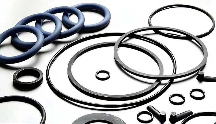
4.1 O-Ring Seals
4.1.1 General Characteristics
O-rings are the most common static sealing element in rough and high vacuum systems. Their advantages include:
- Low cost and wide material availability.
- Simple groove and flange designs.
- Reusability in many applications.
- Compatible with a wide range of media.
O-rings are typically made of elastomeric materials such as FKM, EPDM, NBR, or FFKM, chosen according to chemical resistance, thermal stability, and permeation properties.
4.1.2 Design Considerations
To ensure tight sealing, an O-ring must be installed with controlled compression (squeeze) against its groove. Typical design parameters:
| Parameter | Recommended Range |
|---|---|
| Squeeze (axial or radial) | 15–30% depending on material and application |
| Stretch (ID) | ≤ 5% (higher may cause stress or twist) |
| Surface roughness (Ra) | ≤ 0.8 μm for vacuum-grade sealing surfaces |
| Groove finish | Free of machining marks, scratches, or pits |
Backup rings may be used for higher pressure differentials to prevent extrusion. For UHV applications, O-rings are often housed in double-groove or differential pumping arrangements to control permeation.
4.1.3 Permeation and Outgassing
Unlike metal seals, O-rings permeate gas molecules, especially small ones such as helium and hydrogen. This limits their use in UHV or ultra-clean systems. Typical permeation rates for FKM at room temperature are 10⁻⁷–10⁻⁶ Pa·m³/s·m.
To minimize outgassing:
- Use vacuum-baked or pre-cleaned O-rings.
- Avoid lubricants with high vapor pressures.
- Consider metal-encapsulated elastomer seals for critical interfaces.
4.2 Gasket Seals
4.2.1 Soft Gaskets
Soft gaskets (e.g., PTFE, graphite, expanded PTFE, or composite materials) are common in rough and high vacuum flanges. They conform to surface irregularities and provide reliable sealing at moderate cost.
Advantages:
- Good chemical resistance.
- Suitable for moderate vacuum applications.
- Tolerant to small flange imperfections.
Limitations:
- Limited temperature range.
- Creep or cold flow over time, especially with PTFE.
- Not ideal for repeated disassembly cycles.
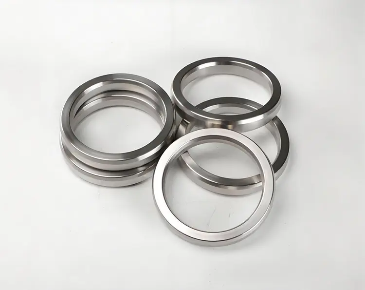
4.2.2 Metal Gaskets
For high and ultra-high vacuum systems, metal gaskets offer unmatched leak tightness and temperature stability. Common configurations include:
- CF (ConFlat) flanges with OFHC copper gaskets — industry standard for UHV.
- C-rings and Helicoflex® seals — resilient metal seals for reusable or higher-load applications.
- Silver- or nickel-plated aluminum or stainless steel for specialized chemical resistance.
Advantages:
- Leak rates < 10⁻¹² Pa·m³/s achievable.
- Excellent bake-out performance (> 200 °C).
- Long service life in static applications.
Limitations:
- Higher initial cost and installation torque.
- CF copper gaskets are single-use (plastically deform).
- Sensitive to flange surface damage.
4.2.3 Flange Standards
Three major flange standards dominate vacuum technology:
| Flange Type | Typical Pressure Range | Typical Seal | Common Use Cases |
|---|---|---|---|
| ISO-KF (NW) | Rough to high vacuum | Elastomer O-ring | Lab systems, small chambers, analytical tools |
| ISO-K | Rough to high vacuum | Elastomer or soft gasket | Large chambers, industrial systems |
| CF | High to ultra-high vacuum | Metal gasket | Semiconductor, UHV research, surface analysis |
Note: The choice of flange standard directly impacts seal selection, bake-out temperature capability, and maintenance procedures.
4.3 Bonded Seals and Other Variants
Bonded seals combine a metal washer and vulcanized elastomer sealing lip, providing a compact design suitable for threaded connections or instrument ports.
They are not typically used in UHV, but they are effective for rough and high vacuum service in auxiliary components such as gauges and feedthroughs.
Variants:
- Dowty® bonded seals (commonly FKM or NBR elastomer).
- Integrated metal-elastomer sealing rings for instrumentation interfaces.
4.4 Failure Modes of Static Seals
Understanding common failure mechanisms helps prevent unplanned downtime:
| Failure Mode | Typical Cause | Mitigation Strategy |
|---|---|---|
| Extrusion / nibbling | Excessive pressure, poor groove design | Use backup rings, control squeeze, improve groove |
| Creep / relaxation | Thermal cycling, incompatible material | Choose low-creep materials, proper torque settings |
| Permeation | Elastomer used in high vacuum | Use metal seals or double-seal differential pumping |
| Surface damage | Scratches, contamination, over-torque | Surface prep, torque control, use soft gaskets |
| Compression set | Over-compression or long service time | Replace aged O-rings, control squeeze |
4.5 Best Practices for Static Seal Installation
- Surface preparation:
- Clean sealing faces with lint-free wipes and solvent.
- Inspect for scratches or dents under good lighting.
- Seal handling:
- Use gloves to avoid contaminating surfaces with oils.
- Avoid stretching or twisting elastomers.
- Torque control:
- Use cross-tightening sequences for flanges.
- Follow manufacturer torque specs to avoid warping.
- Lubrication (optional):
- If needed, use vacuum-compatible lubricants (e.g., PFPE-based).
- Avoid silicone oils and hydrocarbons in UHV systems.
- Bake-out:
- When using elastomers, pre-bake in vacuum ovens to minimize outgassing.
- For metal seals, ensure proper seating before thermal cycling.
4.6 Summary
Static seals form the most reliable and controllable vacuum interfaces in modern systems.
- O-rings and soft gaskets are excellent for rough and high vacuum.
- Metal gaskets dominate UHV due to their low permeation and bake-out capability.
- Surface finish, groove design, and torque control are decisive factors in achieving leak-tight performance.
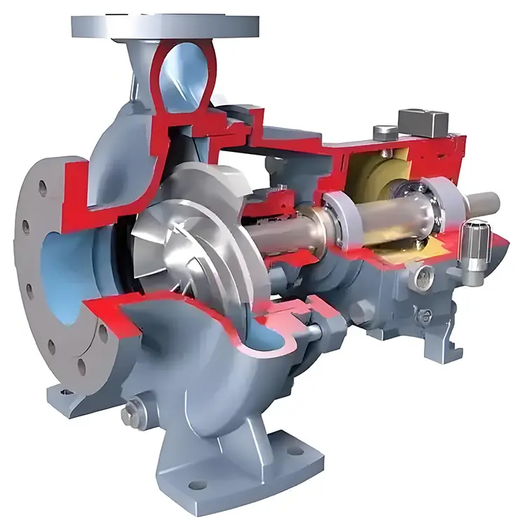
5. Dynamic Sealing Technologies
Dynamic seals operate where one component moves relative to another—most commonly rotating shafts or reciprocating pistons in vacuum pumps, agitators, or feedthroughs.
Unlike static seals, dynamic seals must maintain a stable barrier under mechanical motion, often at high speed, elevated temperature, or in chemically aggressive environments.
Designing and selecting dynamic seals involves balancing sealing integrity, wear resistance, frictional behavior, and service life.
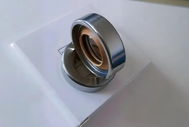
5.1 Mechanical Seals
5.1.1 Principles
A mechanical seal uses the relative sliding of two precisely machined sealing faces — one stationary and one rotating.
A spring or hydraulic pressure maintains face contact, while a very thin fluid film (often in the order of 0.1 to a few micrometers) lubricates the interface.
This controlled interface provides extremely low leakage, suitable for many high vacuum and clean process applications.
Key components:
- Rotating ring (mounted on shaft)
- Stationary ring (mounted in gland or housing)
- Secondary seals (O-rings or bellows)
- Spring or hydraulic loading system
- Drive collar and set screws
5.1.2 Face Material Combinations
Choosing the right face pair is crucial for seal life and leakage performance.
| Face Pairing | Typical Use Case | Characteristics |
|---|---|---|
| SiC vs. Carbon Graphite | Clean and dirty media, general industrial use | Low friction, good thermal shock resistance |
| SiC vs. SiC | High-pressure, abrasive or corrosive media | Very hard, long life, less forgiving to misalignment |
| WC vs. Carbon | High mechanical load, rough vacuum pumps | High strength, moderate wear |
| DLC-coated faces | Clean processes, semiconductor, low particle generation | Low friction, chemical inertness |
5.1.3 Performance Characteristics
- Leakage rates typically 10⁻⁷ – 10⁻⁹ Pa·m³/s, depending on configuration.
- Capable of handling high shaft speeds (> 3,000 rpm) and moderate pressure differentials.
- Dry-running must be avoided: even a few seconds of dry contact can damage seal faces.
Applications:
Dry screw pumps, turbomolecular backing pumps, chemical process equipment, cryo systems.
5.2 Packing Seals
5.2.1 Overview
Packing seals are among the oldest dynamic sealing solutions.
They rely on compressible packing material (e.g., graphite, PTFE, aramid fiber) inserted in a stuffing box around the shaft. The axial compression from a gland follower translates into radial sealing pressure.
Advantages:
- Simple structure and cost-effective.
- Easy to adjust and replace.
- Tolerant to shaft eccentricity or minor surface imperfections.
Limitations:
- Inherent leakage — typically 10⁻⁵ to 10⁻⁷ Pa·m³/s.
- Generates frictional heat; not suitable for high-speed shafts.
- Outgassing and particle shedding make it unsuitable for ultra-clean or UHV systems.
5.2.2 Modern Enhancements
Modern packing materials incorporate braided carbon fiber, PTFE/graphite composites, and expanded graphite rings, improving chemical compatibility and wear resistance.
In some cases, flush or purge gas is used to control ingress or reduce outgassing.
5.3 Lip and Oil Seals
5.3.1 Characteristics
Lip seals (commonly called oil seals) use an elastomeric sealing lip that contacts the rotating shaft, supported by a spring to maintain tension.
They are widely used in rough vacuum applications to prevent air ingress and contain lubricants.
| Feature | Lip Seals |
|---|---|
| Cost | Low |
| Leakage | Moderate (~10⁻⁵ Pa·m³/s typical) |
| Temperature range | Limited (typically -30 to 150 °C) |
| Speed capability | Moderate |
| Cleanliness | Poor for high vacuum |
Limitations:
- High permeation through elastomers.
- Particle generation and outgassing.
- Not suitable for UHV or clean semiconductor environments.
5.4 Labyrinth and Spiral Groove Seals
5.4.1 Principle
Labyrinth seals are non-contacting mechanical structures consisting of a series of grooves or chambers between the shaft and the housing.
They do not form a hermetic seal but create a tortuous path that restricts gas flow.
Spiral groove seals use helical grooves to create a pumping action that drives gas outward, improving performance at high shaft speeds.
Advantages:
- Virtually zero wear.
- Long service life.
- No lubrication required.
Limitations:
- Not tight enough to act as a primary seal in most vacuum systems.
- Commonly used as secondary or buffer seals in combination with mechanical or dry gas seals.
5.4.2 Typical Applications
- High-speed rotary feedthroughs.
- Turbomolecular pumps.
- High-reliability rotating equipment where maintenance access is limited.
5.5 Dry Gas Seals
5.5.1 Operating Principle
Dry gas seals are non-contacting mechanical seals that maintain a very thin gas film (typically 1–3 μm) between the rotating and stationary faces.
This gas film is generated by engineered hydrodynamic grooves that lift the faces apart when the shaft rotates.
- At rest: seal faces are in light contact.
- During operation: gas film forms and minimizes friction.
- Leakage: extremely low and stable, usually a controlled outward flow of inert gas.
5.5.2 Features and Advantages
- Very low leakage (10⁻⁷ – 10⁻⁹ Pa·m³/s).
- Long life due to non-contacting operation.
- Clean — minimal particle generation.
- High-speed capability (> 10,000 rpm possible).
5.5.3 Limitations
- Requires clean, dry buffer gas (e.g., nitrogen).
- Sensitive to contamination.
- Higher upfront cost and design complexity.
5.5.4 Applications
- Dry screw vacuum pumps.
- Large process compressors with vacuum interfaces.
- High-integrity chemical and energy applications.
5.6 Magnetic Fluid (Ferrofluidic) Seals
5.6.1 Principle
Magnetic fluid seals use a ferrofluid held in place by a magnetic field generated by permanent magnets surrounding the shaft.
The ferrofluid creates multiple sealing “stages,” each providing a pressure barrier, allowing ultra-low leakage without physical contact.
Advantages:
- Zero mechanical wear.
- Ultra-clean — ideal for semiconductor or UHV.
- High reliability and long service life.
- Excellent performance for rotating feedthroughs.
Limitations:
- Limited temperature range (typically < 150 °C).
- Sensitive to magnetic field disturbances.
- More expensive than conventional seals.
5.6.2 Applications
- Semiconductor wafer processing.
- Surface science instrumentation.
- UHV analytical systems.
- High-precision rotating feedthroughs.
5.7 Comparative Summary of Dynamic Seals
| Seal Type | Contact | Leakage Rate (Pa·m³/s) | Speed Capability | UHV Suitability | Maintenance | Typical Use Case |
|---|---|---|---|---|---|---|
| Mechanical seal | Yes | 10⁻⁷ – 10⁻⁹ | High | Moderate | Medium | Pumps, agitators |
| Packing seal | Yes | 10⁻⁵ – 10⁻⁷ | Low–Moderate | Poor | Easy | Industrial shafts |
| Lip / oil seal | Yes | ~10⁻⁵ | Moderate | Poor | Easy | Rough vacuum isolation |
| Labyrinth / spiral | No | Moderate | High | Poor | Minimal | Secondary seals, high-speed shafts |
| Dry gas seal | No | 10⁻⁷ – 10⁻⁹ | Very high | Good | Low | Clean process applications |
| Magnetic fluid seal | No | ≤ 10⁻⁹ | High | Excellent | Low | UHV, semiconductor, precision feedthroughs |
5.8 Summary
Dynamic seals are critical enablers of motion under vacuum, combining precision mechanics, material science, and fluid dynamics.
- Mechanical seals are the workhorses of modern vacuum pumps.
- Packing and lip seals serve cost-sensitive or low-vacuum applications.
- Labyrinth and spiral seals offer robust secondary protection.
- Dry gas and magnetic fluid seals represent the cleanest, lowest-leakage technologies available today.
The choice of dynamic seal depends on vacuum level, process cleanliness, speed, maintenance strategy, and cost constraints.
6. Materials & Compatibility
The performance, durability, and leakage behavior of a vacuum seal are determined not only by its geometry but — most critically — by its material composition. Sealing materials must withstand vacuum exposure, resist permeation and outgassing, and maintain their mechanical properties across temperature and pressure extremes.
In vacuum technology, materials are broadly categorized into elastomers, plastics and composites, hard face materials, and metals. Each class brings its own advantages and limitations depending on the vacuum level, medium, and environment.
6.1 Elastomeric Materials
Elastomers are the workhorse materials for static O-rings and some dynamic seals in rough and high vacuum. They are easy to install, cost-effective, and provide reliable sealing — but their inherent permeation and outgassing limit their use in ultra-high vacuum (UHV) and ultra-clean processes.
| Material | Temperature Range (°C) | Permeation | Outgassing | Chemical Resistance | Typical Use |
|---|---|---|---|---|---|
| NBR (Nitrile) | -30 to 120 | High | High | Limited (oils, fuels) | Rough vacuum, general purpose |
| EPDM | -50 to 150 | Moderate | Moderate | Excellent with water/steam, poor with oils | HVAC, industrial |
| FKM (e.g., Viton®) | -20 to 200 | Low | Low | Excellent chemical resistance | High vacuum, chemical systems |
| FFKM (e.g., Kalrez®) | -20 to 280 | Very Low | Very Low | Outstanding | High-purity, aggressive media |
6.1.1 Permeation Behavior
Elastomers are not hermetic: gas molecules permeate through their polymer network over time. Permeation depends on:
- Gas type (He and H₂ permeate most easily)
- Material structure (fluorinated rubbers have lower permeation)
- Thickness and surface area
- Temperature (higher temperatures increase permeability)
For example, helium permeation through FKM O-rings can reach 10⁻⁷ Pa·m³/s·m at room temperature. This is acceptable in many high vacuum systems but not in UHV applications.
6.1.2 Outgassing
Outgassing — the release of trapped volatiles and additives — can raise base pressure and contaminate sensitive processes.
To minimize this:
- Use high-purity vacuum-grade compounds.
- Pre-bake or vacuum bake-out O-rings before installation.
- Avoid materials containing plasticizers or fillers.
6.2 Plastics and Composite Materials
Engineering plastics offer low permeability, broad chemical resistance, and dimensional stability at elevated temperatures. However, they may exhibit creep or cold flow, especially under constant compression.
| Material | Temperature Range (°C) | Permeation | Chemical Resistance | Key Properties |
|---|---|---|---|---|
| PTFE (Teflon®) | -200 to 250 | Very Low | Excellent | Chemically inert, but cold flow |
| PCTFE | -200 to 150 | Very Low | Excellent | Lower cold flow than PTFE |
| PEEK | -50 to 250 | Very Low | Excellent | High strength, machinable |
| Graphite composites | Up to 500+ | Very Low | Excellent | High temperature tolerance |
6.2.1 PTFE and PCTFE
PTFE is widely used for soft gaskets, envelope seals, and backup rings. It has extremely low outgassing and chemical inertness.
Its drawback is cold flow — it can deform under long-term compression, potentially reducing sealing stress.
PCTFE offers better dimensional stability than PTFE, making it suitable for applications with long service intervals.
6.2.2 PEEK
PEEK combines high mechanical strength with low permeability, making it a suitable alternative for structural sealing components, valve seats, and high-load interfaces.
6.3 Hard Face Materials
Dynamic seals often rely on hard, wear-resistant face materials to minimize leakage and extend service life. The selection of the face pair is a critical engineering decision.
| Material | Hardness | Chemical Resistance | Thermal Shock | Application |
|---|---|---|---|---|
| Silicon Carbide (SiC) | Very high | Excellent | Good | Mechanical seals, abrasive media |
| Tungsten Carbide (WC) | Very high | Good | Moderate | High-load applications |
| Carbon Graphite | Low–Medium | Excellent | Excellent | Mating face, forgiving to misalignment |
| DLC Coatings | Very high | Excellent | Excellent | Semiconductor, ultra-clean applications |
- SiC–Graphite is one of the most widely used pairings, combining low friction and good thermal shock resistance.
- SiC–SiC offers very long wear life but is less forgiving to contamination or misalignment.
- DLC-coated surfaces reduce friction and particulate generation.
6.4 Metal Materials
Metallic seals are indispensable for UHV and extreme environments due to their zero permeation, high temperature capability, and excellent bake-out performance.
| Material | Temp Limit (°C) | Leak Rate | Typical Use |
|---|---|---|---|
| OFHC Copper | > 450 | < 10⁻¹² Pa·m³/s | CF flanges, UHV viewports |
| Stainless Steel (304/316L) | > 400 | < 10⁻¹² Pa·m³/s | Metal gaskets, welded joints |
| Aluminum (plated) | 300+ | Very low | Lightweight systems, secondary seals |
| Nickel alloys | High | Very low | Corrosive or cryogenic applications |
6.4.1 Copper Gaskets
Oxygen-Free High Conductivity (OFHC) copper is the standard gasket material for CF flanges. It plastically deforms upon tightening, filling microscopic imperfections and achieving extremely low leak rates.
6.4.2 Metal C-Rings and Helicoflex® Seals
For reusable or high-load sealing, resilient metal seals like C-rings or Helicoflex® are used. They combine a metal jacket with an elastic core, enabling multiple cycles without sacrificing leak integrity.
6.5 Hygienic and Regulatory Considerations
In industries such as pharmaceuticals, food processing, or biotechnology, sealing materials must meet strict sanitary standards:
- FDA CFR 21 177.2600 (food-grade elastomers)
- USP Class VI (biocompatibility)
- ISO 10993 (medical devices)
Materials must:
- Resist cleaning and sterilization cycles (e.g., SIP/CIP).
- Avoid extractables and leachables that can contaminate products.
- Maintain elasticity after repeated thermal cycling.
Typical choices: platinum-cured silicone, EPDM (peroxide-cured), and FFKM for aggressive chemicals.
6.6 Quick Compatibility Matrix
| Material Type | Vacuum Suitability | Thermal Limit | Chemical Resistance | Permeation | Typical Application |
|---|---|---|---|---|---|
| NBR | Rough vacuum | Low | Poor–Moderate | High | Utility connections |
| EPDM | High vacuum | Moderate | Good (steam, water) | Moderate | Industrial processes |
| FKM | High vacuum | High | Excellent | Low | General-purpose sealing |
| FFKM | High/UHV | Very High | Outstanding | Very Low | Semiconductor, corrosive |
| PTFE/PCTFE | High/UHV | High | Excellent | Very Low | Soft gaskets, lining |
| Metals | UHV and above | Very High | Excellent | None | CF flanges, permanent seals |
6.7 Summary
The right sealing material determines:
- Leak tightness
- Service life
- Compatibility with the operating environment
- Maintenance frequency and cost.
- Elastomers are flexible and cost-effective but permeable.
- Plastics offer low outgassing and chemical inertness but may creep.
- Hard face materials ensure durability in dynamic seals.
- Metals are the gold standard for UHV and harsh conditions.
Material selection must align with vacuum level, process chemistry, thermal environment, and regulatory requirements.
7. Seal Selection Framework
Choosing the correct sealing solution for a vacuum system is not a one-size-fits-all process. It requires a structured, multi-criteria evaluation that considers both technical performance and operational practicality. A well-defined selection framework ensures consistent sealing performance, reduces downtime, and avoids premature failures that can compromise vacuum integrity.
7.1 Defining Operational Requirements
Before any material or design is selected, the operating conditions must be clearly defined. This step is often overlooked, but it determines the entire sealing strategy.
Key parameters to document include:
| Parameter | Examples / Typical Ranges | Impact on Seal Selection |
|---|---|---|
| Vacuum level | Rough, high, UHV | Determines allowable permeation and outgassing |
| Media | Air, inert gas, corrosive chemicals, solvents, steam | Drives material compatibility and seal configuration |
| Pressure differential | Ambient to vacuum, or positive/negative differential | Influences seal geometry and backup structure |
| Temperature range | Cryogenic to 300+ °C | Determines elastomer, plastic, or metal suitability |
| Motion | Static, reciprocating, rotating | Determines dynamic vs static sealing technology |
| Speed | 0 to 30,000+ rpm | Affects frictional heat, wear, and seal type |
| Cleanliness requirements | Semiconductor-grade, general industrial | Affects material selection and leakage tolerance |
| Maintenance strategy | Preventive, predictive, minimal-access | Impacts seal life and reusability requirements |
7.2 Decision Path: Static vs. Dynamic
The first major decision in the framework is whether the interface is static or dynamic:
- Static interfaces (e.g., flanges, viewports, chamber covers):
→ Favor elastomer O-rings (rough/high vacuum) or metal gaskets (UHV). - Dynamic interfaces (e.g., shafts, moving rods):
→ Require mechanical seals, packing, or advanced non-contact seals.
Tip: Whenever possible, avoid dynamic sealing in UHV environments — motion significantly increases leakage risk. If unavoidable, consider magnetic fluid or dry gas seals.
7.3 Vacuum Level and Permeation Tolerance
The vacuum class dictates how much leakage and permeation can be tolerated.
| Vacuum Level | Typical Max Leakage | Recommended Seal Types |
|---|---|---|
| Rough Vacuum (10⁵ – 10² Pa) | ~10⁻⁵ Pa·m³/s | Elastomer O-rings, gaskets, packing |
| High Vacuum (10² – 10⁻³ Pa) | ≤ 10⁻⁸ Pa·m³/s | FKM/FFKM O-rings, soft gaskets, mechanical seals |
| Ultra-High Vacuum (10⁻³ – 10⁻⁹ Pa) | ≤ 10⁻¹⁰ Pa·m³/s | Metal gaskets, dry gas seals, welded joints |
| UHV+ / Extreme | < 10⁻¹¹ Pa·m³/s | Metal C-rings, CF flanges, ferrofluidic seals |
- If permeation tolerance is high, elastomers may be acceptable.
- If permeation must be near zero, metal or hybrid seals are required.
7.4 Chemical and Thermal Environment
Chemical compatibility is often the limiting factor in seal selection. Examples:
- Strong acids or solvents → PTFE or FFKM.
- Steam sterilization → EPDM or platinum-cured silicone.
- High temperature (>250 °C) → metals or high-performance plastics.
- Cryogenic → PCTFE, metals, or custom elastomers.
Thermal cycles also cause seal creep, compression set, or differential expansion between flange materials. This must be accounted for during design, particularly for soft gaskets or elastomers.
7.5 Motion and Speed Considerations
If the sealing interface involves motion:
| Motion Type | Typical Seal Types | Notes |
|---|---|---|
| None (static) | O-rings, gaskets, metal seals | Highest sealing performance |
| Reciprocating | Packing, bellows seals, linear feedthrough seals | Control stroke and lubrication |
| Rotational (low speed) | Packing, mechanical seals, lip seals | Consider frictional heat |
| Rotational (high speed) | Mechanical seals, dry gas seals, ferrofluidic seals | Non-contact preferred for clean systems |
For high-speed shafts, non-contact solutions like dry gas or magnetic fluid seals provide the best combination of low wear and low leakage.
7.6 Maintenance and Service Strategy
The expected maintenance interval and system accessibility strongly influence seal selection:
- Short maintenance intervals → Elastomer O-rings or packing may be acceptable.
- Long maintenance intervals / limited access → Favor metal gaskets or ferrofluidic seals for long-term stability.
- Predictive maintenance (condition-based) → Allows use of advanced mechanical or dry gas seals with monitoring.
Example: Semiconductor process chambers often use CF copper gaskets because the cost of downtime outweighs the higher installation effort.
7.7 Cost vs. Performance Trade-Off
The lowest initial cost is not always the lowest total cost of ownership (TCO). Key cost drivers include:
- Frequency of seal replacement.
- Downtime and venting cycles.
- Energy or gas costs (e.g., buffer gas).
- Cleanroom contamination events.
| Seal Type | Initial Cost | Maintenance Frequency | Typical Lifetime | TCO Profile |
|---|---|---|---|---|
| O-ring (FKM) | Low | Frequent (months–1 yr) | 6–12 months | Low upfront, high maintenance |
| Metal gasket (CF) | Moderate | Rare (years) | 5+ years | High reliability, low downtime |
| Dry gas seal | High | Rare, monitored | 3–10 years | Low leakage, high capex |
| Magnetic fluid seal | High | Very rare | 5–15 years | Longest life, ultra-clean |
7.8 Decision Tree Example
Below is a simplified logical flow for selecting a seal type:
- Static or dynamic interface?
- Static → go to 2
- Dynamic → go to 5
- Required vacuum level:
- Rough/High → Elastomer O-ring or soft gasket
- UHV → Metal gasket or welded joint
- Chemical/thermal constraints:
- High → PTFE or metal
- Moderate → FKM or EPDM
- Maintenance interval:
- Short → Elastomer acceptable
- Long → Metal gasket preferred
- Dynamic sealing:
- Low speed → Packing or mechanical seal
- High speed → Dry gas or magnetic fluid seal
- Cleanroom/UHV?
- Yes → Non-contact or metal sealing
- No → Packing or elastomer acceptable
(In the published version, this step would be illustrated with a flowchart.)
7.9 Example Configurations
| Scenario | Key Constraints | Recommended Sealing Solution |
|---|---|---|
| Rough vacuum drying chamber | Low vacuum, low temperature | NBR O-ring or soft PTFE gasket |
| High vacuum chemical process | Aggressive solvent vapors | FFKM O-ring + mechanical seal |
| UHV analytical chamber | Bake-out at 250 °C | CF flange + OFHC copper gasket |
| High-speed rotary shaft in clean process | High rpm, low contamination tolerance | Dry gas seal + labyrinth buffer |
| Semiconductor wafer handling feedthrough | UHV, ultra-clean | Magnetic fluid seal |
7.10 Summary
A systematic seal selection framework ensures technical suitability and economic efficiency:
- Step 1: Define operating conditions (vacuum, media, temperature, motion).
- Step 2: Choose static vs dynamic sealing approach.
- Step 3: Match material and seal type to vacuum class and environment.
- Step 4: Factor in maintenance intervals, accessibility, and cost.
- Step 5: Validate with practical test or qualification data.
A well-chosen seal minimizes leaks, extends service life, and reduces overall cost of ownership.
8. Design & Installation Best Practices
Even the best sealing materials and configurations can fail if installation and interface design are not carefully controlled. Many vacuum leaks are not caused by the seal itself but by improper surface preparation, inaccurate groove dimensions, or incorrect torque application.
This chapter covers the engineering principles and field practices that ensure a seal performs to its design specifications over its entire service life.
8.1 Surface Preparation and Finish
8.1.1 Importance of Surface Finish
A vacuum seal relies on intimate contact between the sealing material and the flange or housing. Microscopic surface defects such as scratches, pits, or machining marks can create leak paths.
| Parameter | Recommendation | Notes |
|---|---|---|
| Surface roughness (Ra) | ≤ 0.8 μm for elastomers≤ 0.4 μm for metal seals | Smoother finishes yield lower leak rates |
| Flatness | < 0.05 mm across flange face | Critical for metal gaskets and CF flanges |
| Cleanliness | Particle- and oil-free | Contamination can cause outgassing and leak paths |
8.1.2 Cleaning Procedure
- Clean with solvent (e.g., isopropanol) and lint-free wipes.
- Avoid touching sealing surfaces with bare hands.
- For UHV, perform ultrasonic cleaning and bake-out of components.
- Inspect under good lighting or magnification.
8.2 Groove and Gland Design
8.2.1 O-Ring and Elastomer Seals
Groove design governs sealing compression, extrusion resistance, and dimensional stability. Common mistakes include over-compression (leading to permanent set) and under-compression (leading to leaks).
| Design Parameter | Typical Range | Effect |
|---|---|---|
| Squeeze (axial/radial) | 15–30% | Too high → stress and cracking; too low → leakage |
| Stretch | ≤ 5% | Excessive stretch distorts cross-section |
| Groove clearance | Minimized, may use backup rings | Reduces extrusion under pressure |
| Corner design | Rounded edges (R ≥ 0.2 mm) | Prevents O-ring damage during installation |
8.2.2 Metal Seals
Metal gaskets (e.g., copper CF) require:
- Flat, clean, knife-edge flanges.
- Proper alignment during assembly.
- Controlled torque to avoid edge deformation.
Helicoflex® or C-ring seals require precise groove depth and width, ensuring controlled elastic compression.
8.3 Concentricity and Alignment
Poor alignment between sealing surfaces is a major cause of installation leaks and premature seal wear in dynamic systems.
- Ensure shaft runout < 0.05 mm for mechanical seals.
- Use precision dowel pins or alignment features on large flanges.
- In dynamic assemblies, alignment reduces uneven loading and localized wear.
Tip: Misalignment issues often mimic “seal failure” but are actually system design flaws.
8.4 Torque Application and Fastening
Correct and uniform torque ensures:
- Even gasket compression.
- Proper face deformation (for metal gaskets).
- Prevention of flange distortion.
8.4.1 Torque Best Practices
- Use a calibrated torque wrench.
- Tighten bolts in a star or criss-cross pattern to distribute load evenly.
- Increase torque in multiple passes (e.g., 30%, 60%, 100% of target).
- Follow manufacturer torque specs or experimentally validated values.
- For large flanges, retorque after thermal cycling.
| Seal Type | Typical Torque Behavior |
|---|---|
| Elastomer O-ring | Relatively forgiving, uniform compression key |
| Soft gasket | Torque must account for creep and relaxation |
| Metal gasket (CF) | Precise torque critical for knife-edge engagement |
8.5 Lubrication and Assembly Aids
- Use only vacuum-compatible lubricants, e.g., PFPE-based (perfluoropolyether).
- Avoid hydrocarbon oils or greases, which outgas heavily under vacuum.
- Light lubrication helps prevent O-ring twisting and installation damage.
- For metal seals, lubrication is usually unnecessary or limited to thread lubrication to achieve consistent bolt tension.
Note: In UHV applications, it’s often preferable to assemble seals dry or with minimal lubricant to reduce contamination risk.
8.6 Handling and Storage of Seals
Improper storage is a hidden cause of seal degradation, especially for elastomers.
Recommended practices:
- Store in cool, dark, and dry environments.
- Keep away from ozone sources (e.g., electrical equipment).
- Use sealed bags to prevent contamination.
- Mark storage and shelf life dates — elastomers can age even unused.
- Avoid excessive stretching or folding of seals during handling.
8.7 Pre-Startup Checks
Before starting the vacuum system, always perform the following:
- Visual inspection of flange alignment, bolts, and seal placement.
- Helium leak check around critical joints (especially UHV).
- Pressure rise test for rough vacuum validation.
- Confirm seal compression or torque values are within tolerance.
- For dynamic seals, ensure lubrication and shaft rotation tests are smooth.
A single pre-start check can prevent hours of costly venting and rework.
8.8 Design Considerations for Serviceability
When designing vacuum systems, consider not only performance but also ease of maintenance:
- Modular flange assemblies allow seal replacement without full disassembly.
- Use standardized flange types and seal sizes.
- Provide access clearance for torque tools and leak detectors.
- Minimize blind holes and trapped volumes to reduce virtual leaks.
These design considerations improve long-term reliability and reduce downtime.
8.9 Bake-Out and Thermal Cycling
Bake-out is commonly used to reduce outgassing and improve vacuum performance.
| Seal Type | Bake-Out Range | Notes |
|---|---|---|
| Elastomer (FKM) | ≤ 200 °C | Pre-bake separately before installation if possible |
| PTFE / PCTFE | 250 °C | Low outgassing, minimal degradation |
| Metal gaskets | ≥ 400 °C | Compatible with UHV bake-out |
- Gradual heating and cooling minimize thermal stress on seals.
- Check torque and alignment after bake-out, especially for soft or elastomeric seals.
- For UHV systems, bake-out is often combined with helium leak testing.
8.10 Typical Installation Errors to Avoid
| Common Error | Consequence | Prevention Tip |
|---|---|---|
| Over-tightening flange bolts | Distorted flange, damaged gasket | Use torque wrench and proper sequence |
| Under-tightening | Poor compression, leaks | Follow validated torque specs |
| Poor surface cleaning | Outgassing, microleaks | Clean with approved solvents |
| O-ring twisted during installation | Spiral failure, uneven compression | Light lubrication and proper seating |
| Misalignment in dynamic systems | Uneven wear, early seal failure | Check shaft runout, concentricity |
| Using incompatible lubricants | Outgassing, contamination | Use PFPE or approved vacuum-grade lubricants |
| Reusing damaged gaskets or aged elastomers | Leaks under vacuum | Replace with new components |
8.11 Summary
Seal design and installation are as critical as material selection in achieving vacuum integrity. Key principles include:
- Ensuring precision in surface finish, alignment, and groove design.
- Applying controlled torque and using proper assembly sequences.
- Maintaining cleanliness and using vacuum-compatible lubricants.
- Performing pre-start leak checks to catch issues early.
- Designing for serviceability to minimize downtime.
When executed correctly, these practices dramatically increase seal reliability, reduce leakage rates, and extend the service life of the vacuum system.
9. Commissioning, Operation & Monitoring
Even the most carefully selected and precisely installed seal can underperform if the commissioning and operational phase is not properly managed. Vacuum systems are particularly sensitive to startup conditions, temperature fluctuations, contamination, and misaligned operational practices.
This chapter focuses on best practices for bringing sealed vacuum systems online, monitoring performance during operation, and detecting early warning signs of seal degradation.
9.1 Pre-Startup Commissioning Checks
Before the first pump-down, perform a structured verification of the entire sealing system. A methodical commissioning procedure can prevent 80% of early seal failures.
9.1.1 Mechanical Verification
- Inspect all flange bolts for correct torque values.
- Confirm alignment between mating components (especially shaft and gland interfaces).
- Verify that O-rings or gaskets are seated correctly with no twists, cuts, or extrusion.
- Ensure all backup rings, spacers, and retainers are properly positioned.
9.1.2 System Cleaning
- Verify all seal contact surfaces are free of dust, oil, and fingerprints.
- Flush the chamber with clean, dry nitrogen (or other inert gas) to remove particulates.
- Ensure lubricants, if used, are vacuum-compatible (PFPE-based or approved equivalents).
9.1.3 Leak Testing Before Pumping
- Perform an initial helium leak check around all critical joints.
- Use pressure rise test for rough verification in non-critical zones.
- Acceptable leak rates should align with the target vacuum level:
- Rough vacuum: ≤ 10⁻⁵ Pa·m³/s
- High vacuum: ≤ 10⁻⁸ Pa·m³/s
- UHV: ≤ 10⁻¹⁰ Pa·m³/s
Tip: Always test for leaks before the system is fully assembled or covered with insulation — this makes fixing issues far easier.
9.2 Controlled Pump-Down Procedure
A controlled evacuation minimizes mechanical and thermal stresses on seals.
- Purge the system with inert gas to remove atmospheric moisture and contaminants.
- Start the backing pump slowly, ensuring stable evacuation and avoiding pressure shocks.
- Monitor the pressure gradient to detect abnormal outgassing or leaks.
- For systems with elastomer seals, allow time for initial outgassing before transitioning to high vacuum.
- For UHV systems, follow with a bake-out phase to accelerate desorption from surfaces.
Common commissioning mistake: Rapid evacuation of large chambers can cause seal inversion (O-ring being pulled from the groove) or face distortion in metal seals. A gradual pump-down avoids this.
9.3 Initial Stabilization and Break-In
Many seals, particularly mechanical and dry gas seals, have a short break-in period during which minor leakage may be observed.
- Stabilization usually occurs within minutes to hours of operation.
- Temperature should be monitored closely; a moderate increase is normal as friction stabilizes.
- Persistent leakage after the break-in period indicates:
- Improper face loading or misalignment (mechanical seals).
- Damaged O-ring seating.
- Inadequate torque or flange distortion.
9.4 Operational Monitoring Parameters
9.4.1 Temperature Monitoring
- Place thermocouples or RTDs near seal interfaces (especially dynamic seals).
- Watch for temperature spikes, which can indicate friction, contamination, or insufficient lubrication.
- A slow drift upward may indicate wear or gas ingress, while sudden jumps may signal failure.
9.4.2 Vibration Monitoring
- Shaft vibration is a common early symptom of dynamic seal issues.
- Vibration can cause uneven face loading, increased wear, and accelerated leakage.
- Install vibration sensors near rotating equipment.
9.4.3 Pressure and Leak Rate Tracking
- Continuously monitor base pressure and pump-down curves.
- A stable base pressure over time indicates healthy sealing and low outgassing.
- A rising base pressure or longer pump-down time is often the first sign of:
- O-ring aging or cracking.
- Packing seal wear.
- Outgassing from contamination.
| Parameter | Normal Behavior | Warning Sign |
|---|---|---|
| Base pressure | Stable at spec | Gradual or sudden rise |
| Pump-down curve | Consistent repeatability | Delayed or irregular evacuation |
| Seal temperature | Stable, predictable trend | Fluctuations, sudden spikes |
| Vibration amplitude | Low, stable | Increasing amplitude, irregular frequencies |
9.5 Helium Leak Detection During Operation
Helium leak testing isn’t just for commissioning — it’s an excellent diagnostic tool during normal operation or troubleshooting.
Best practices:
- Test around high-stress or high-temperature zones first.
- Use sniffing mode for large systems and vacuum mode for precise location.
- Correlate leak readings with pressure and temperature trends.
- Record test results for trend analysis over time.
Note: Slow increases in helium background can indicate gradual permeation or early-stage seal degradation.
9.6 Preventing Operational Seal Degradation
Seal degradation often occurs gradually, making it harder to detect until failure.
Key operational safeguards include:
- Avoid dry running of mechanical or dynamic seals.
- Keep sealing surfaces clean — contamination accelerates wear.
- Maintain stable temperature and pressure profiles to minimize thermal cycling stress.
- Use buffer or barrier gases for dry gas seals as specified by the manufacturer.
- Avoid over-tightening or overtensioning during maintenance.
For elastomer O-rings:
- Limit exposure to aggressive chemicals.
- Prevent prolonged compression at elevated temperature to reduce permanent set.
- Replace seals proactively during scheduled maintenance, not only after failure.
9.7 Integration with Predictive Maintenance Systems
Modern vacuum installations increasingly use condition monitoring to detect seal degradation before it leads to leaks.
Common methods include:
- Real-time temperature and vibration sensors.
- Helium leak detection logging.
- Automated base pressure trending.
- Threshold-based alarm systems.
Advanced systems may integrate machine learning algorithms to predict failure patterns, especially for critical rotating equipment using mechanical or dry gas seals.
9.8 Emergency Response and Troubleshooting
If an unexpected leak occurs during operation:
- Isolate the affected zone quickly to minimize contamination.
- Check for temperature or vibration anomalies near the seal.
- Perform localized helium leak testing to identify the source.
- If the system uses metal gaskets, re-torquing may resolve minor leaks.
- If the seal is elastomeric, venting and replacement may be required.
Important: Do not apply excessive torque or sealant compounds as a “quick fix” — this often makes the problem worse or damages the flange.
9.9 Documentation and Trending
Good sealing performance is achieved not only through engineering but also through data discipline:
- Record torque values, leak rates, bake-out conditions, and startup pressures.
- Maintain a seal performance log to identify gradual performance drift.
- Schedule periodic leak checks and inspections based on service intervals.
A documented history allows engineers to predict seal replacement cycles, reducing unplanned downtime.
9.10 Summary
Successful seal operation is not just about correct installation — it’s about active management during the system’s life cycle:
- Verify alignment, cleanliness, and leak integrity during commissioning.
- Control pump-down rates to protect seals from pressure shocks.
- Monitor temperature, vibration, and pressure for early failure signs.
- Use helium leak detection as both a commissioning and operational tool.
- Integrate monitoring and documentation for predictive maintenance.
10. Maintenance Strategy
In vacuum systems, seals are both critical components and consumable elements. Their performance directly determines whether the system can achieve and maintain the required vacuum level. A well-structured maintenance strategy is therefore essential to maximize uptime, minimize leaks, and ensure long service life for both seals and equipment.
This chapter outlines preventive, predictive, and corrective maintenance strategies, including practical inspection methods and maintenance planning frameworks.
10.1 Maintenance Philosophy: Preventive vs. Predictive vs. Corrective
| Strategy | Description | Advantages | Drawbacks |
|---|---|---|---|
| Preventive Maintenance | Scheduled inspection and replacement at fixed intervals. | Reduces unexpected downtime, simple to plan. | May replace seals earlier than necessary. |
| Predictive Maintenance | Monitors condition (temperature, leak rate, vibration) to replace seals just before failure. | Maximizes seal life, minimizes unplanned stops. | Requires sensors and monitoring infrastructure. |
| Corrective Maintenance | Replace or repair seals after failure occurs. | Low short-term cost. | High risk of downtime, contamination, and equipment damage. |
Most modern vacuum systems benefit from a hybrid approach, combining preventive scheduling with predictive monitoring for critical seals.
10.2 Maintenance Planning and Interval Definition
10.2.1 Defining Service Intervals
Service intervals should be set based on:
- Seal type and expected service life.
- Operating vacuum level and contamination risk.
- Process conditions (temperature, chemical exposure, mechanical load).
- Manufacturer recommendations and field experience.
| Seal Type | Typical Service Interval | Notes |
|---|---|---|
| Elastomer O-rings | 6–12 months | Shorter under chemical or thermal stress. |
| Soft gaskets (PTFE) | 1–2 years | Check for creep or cold flow at each shutdown. |
| Metal gaskets (CF) | 3–5+ years | Often replaced only during major maintenance cycles. |
| Mechanical seals | 2–5 years | Subject to face wear monitoring. |
| Dry gas seals | 3–10 years | Typically monitored, not replaced on schedule. |
| Ferrofluidic seals | 5–15 years | Minimal maintenance, replace only upon performance drop. |
10.3 Preventive Maintenance Activities
Preventive maintenance focuses on planned inspections and proactive replacement of seals before failure.
Typical tasks include:
- Visual inspection for cracks, flattening, or wear.
- Measuring compression set in O-rings.
- Replacing elastomers at scheduled intervals even if no visible defect exists.
- Inspecting flange faces for scratches or contamination.
- Retorquing bolts on metal seals after bake-out or thermal cycles.
- Documenting all replacements and test results.
Tip: For critical systems, preventive seal replacement should coincide with other scheduled maintenance to minimize downtime.
10.4 Predictive Maintenance and Condition Monitoring
Predictive maintenance relies on real-time or periodic measurement of parameters that indicate seal degradation.
| Indicator | What It Reveals | Tools / Methods |
|---|---|---|
| Helium leak rate | Onset of leakage/permeation increase | Helium leak detector, sniffing or vacuum mode |
| Base pressure drift | Seal wear or contamination | Pressure gauges, residual gas analysis |
| Temperature rise | Mechanical friction, misalignment | Thermocouples, RTDs near seal faces |
| Vibration amplitude | Shaft misalignment, mechanical seal degradation | Accelerometers or vibration monitoring systems |
| Pump-down time changes | Outgassing or growing leaks | Process log trends |
10.4.1 Monitoring Frequency
- High-value UHV systems: Continuous or daily monitoring.
- Industrial systems: Weekly or monthly depending on process criticality.
- Non-critical systems: Periodic checks aligned with maintenance windows.
Trend analysis is often more valuable than absolute numbers. Gradual changes in baseline behavior are early warning signs of seal degradation.
10.5 Maintenance Procedures for Different Seal Types
10.5.1 Elastomer O-Rings
- Replace proactively during scheduled shutdowns.
- Inspect for hardening, flattening, or surface cracks.
- Clean grooves and sealing surfaces thoroughly before reinstallation.
- Use fresh, vacuum-compatible lubricants if required.
- Document installation date and torque.
10.5.2 Soft and Metal Gaskets
- Inspect flange knife edges for burrs or scratches.
- Always use new copper gaskets for CF flanges (do not reuse).
- Retorque bolts after bake-out to compensate for gasket relaxation.
- For Helicoflex® seals, follow manufacturer’s compression specifications carefully.
10.5.3 Mechanical Seals
- Inspect face wear, spring integrity, and secondary O-rings.
- Check shaft runout and alignment during reassembly.
- Replace worn faces or springs, not just elastomers.
- Requalify with a helium leak test post-installation.
10.5.4 Dry Gas Seals
- Inspect seal gas supply system for cleanliness and proper pressure.
- Check grooves for contamination or damage.
- Replace only if leakage trend exceeds acceptable limits.
10.5.5 Ferrofluidic Seals
- Verify magnetic field strength and ferrofluid integrity.
- Check for contamination or degradation signs.
- Typically replaced after extended service life, not on schedule.
10.6 Spare Parts Management and Shelf Life
Seal storage conditions directly affect their performance and reliability.
Best practices:
- Store elastomers in sealed bags in cool, dark, ozone-free environments.
- Use first in, first out (FIFO) inventory management.
- Label storage and expiration dates.
- Avoid folding or stretching seals in storage.
- Keep metal gaskets clean and free of oxidation.
| Material Type | Typical Shelf Life | Storage Notes |
|---|---|---|
| NBR / EPDM | 3–5 years | Sensitive to ozone and UV |
| FKM / FFKM | 5–10 years | Good stability, but store away from heat |
| PTFE / PEEK | 10+ years | Inert, but avoid deformation |
| Metal gaskets | Indefinite | Keep dry and free of scratches |
10.7 Documentation and Maintenance Records
Consistent recordkeeping enables better maintenance decisions and predictive analysis.
Recommended record fields:
- Seal type, material, manufacturer.
- Installation date and torque.
- Leak rates at installation and post-bake.
- Maintenance and replacement dates.
- Operational anomalies (temperature spikes, pressure drift, etc.).
- Inspection results and corrective actions taken.
This data allows engineers to optimize replacement intervals, predict failure, and standardize maintenance procedures across multiple systems.
10.8 Failure Mode Analysis and Lessons Learned
When a seal does fail unexpectedly, analyzing the root cause helps prevent recurrence.
Typical failure mechanisms include:
| Failure Mode | Common Cause | Preventive Action |
|---|---|---|
| Permanent set (elastomer) | Over-compression, long service time | Controlled squeeze, regular replacement |
| Extrusion or nibbling | High pressure, poor groove design | Backup rings, groove redesign |
| Permeation | Elastomer in UHV | Switch to metal or FFKM |
| Surface scratching (metal seals) | Over-torque, poor handling | Torque control, clean surfaces |
| Mechanical seal leakage | Misalignment, face wear, dry running | Shaft alignment, monitoring, lubrication control |
Root cause analysis (RCA) should be documented, and corrective actions built into the next maintenance plan.
10.9 Optimizing Maintenance Costs and Uptime
- Bundle maintenance activities (e.g., seal replacement, cleaning, recalibration) to minimize venting cycles.
- Use predictive data to extend intervals safely rather than replacing on rigid schedules.
- For high-value systems, invest in condition monitoring to prevent costly unplanned downtime.
- Establish critical spare part kits for rapid response.
Cost-effective maintenance does not mean doing less — it means doing the right work at the right time.
10.10 Summary
A robust maintenance strategy is a key enabler of long-term vacuum system reliability:
- Preventive maintenance reduces unexpected downtime.
- Predictive monitoring allows maximum seal utilization with minimal risk.
- Proper spare part management ensures readiness.
- Failure analysis strengthens future performance.
When implemented consistently, maintenance planning extends seal service life, stabilizes base pressure, and lowers total cost of ownership.
11. Sector-Specific Guidance
Vacuum sealing strategies vary significantly across industries. While the underlying principles of leakage control, material compatibility, and proper installation remain constant, each sector imposes unique performance, cleanliness, and regulatory requirements.
This chapter examines how seal selection and management strategies are adapted to meet the specific operational demands of key vacuum-dependent industries.
11.1 Semiconductor and Ultra-High Vacuum (UHV) Applications
11.1.1 Key Requirements
- Leak rate: Typically below 1 × 10⁻¹⁰ Pa·m³/s per joint.
- Outgassing: Extremely low — even trace volatiles can contaminate wafers or thin films.
- Bake-out capability: 200–400 °C.
- Cleanliness: ISO Class 1–5 cleanroom compatibility.
- Elastomer avoidance: Wherever possible to minimize permeation.
11.1.2 Recommended Sealing Strategies
- All-metal seals — OFHC copper CF gaskets, C-rings, Helicoflex® for critical interfaces.
- Welded or brazed joints for permanent installations (viewports, feedthroughs).
- Ferrofluidic seals for rotary motion; clean, low-leakage, and UHV compatible.
- Double-seal configurations with differential pumping for any remaining elastomer interfaces.
11.1.3 Operational Practices
- Pre-bake seals and components before integration.
- Implement rigorous helium leak testing at every maintenance cycle.
- Maintain tight torque control and flange alignment.
- Avoid use of greases or lubricants unless explicitly vacuum qualified.
Example:
In a wafer etching system, ferrofluidic rotary feedthroughs are paired with CF copper gaskets on all static flanges. No elastomer seals are used inside the process volume to prevent contamination and pressure drift.
11.2 Chemical Processing and Corrosive Media
11.2.1 Key Requirements
- Chemical compatibility: Seals must resist acids, solvents, and aggressive vapors.
- Thermal cycling: Frequent heating and cooling cycles during batch processing.
- Moderate vacuum levels: Typically high vacuum or rough vacuum.
- Ease of maintenance: Frequent system access for cleaning and inspection.
11.2.2 Recommended Sealing Strategies
- FFKM O-rings for aggressive chemicals and high-temperature environments.
- PTFE envelope gaskets or composite seals for flange connections.
- SiC / graphite mechanical seals for rotary shafts, resistant to chemical attack.
- Dry gas seals with barrier gases in critical pump applications.
11.2.3 Operational Practices
- Regular inspection and scheduled elastomer replacement due to chemical aging.
- Use purge or barrier gas systems to protect dynamic seals from corrosive ingress.
- Clean and flush sealing surfaces during every shutdown to remove residue.
- Monitor pressure and leak rate trends closely for early signs of degradation.
Example:
In a chemical vapor deposition (CVD) reactor, FFKM elastomer seals are used on static flanges, while dry gas seals with nitrogen purge protect the pump shaft from corrosive by-products.
11.3 Pharmaceutical and Food Processing
11.3.1 Key Requirements
- Regulatory compliance: FDA, USP Class VI, and ISO 10993 for hygienic applications.
- CIP/SIP compatibility: Clean-in-place and steam-in-place sterilization cycles.
- Material safety: Non-toxic, non-leaching, and traceable.
- Easy disassembly and cleaning.
11.3.2 Recommended Sealing Strategies
- EPDM or platinum-cured silicone O-rings for hygienic ports and access covers.
- PTFE gaskets in areas requiring frequent sterilization or chemical resistance.
- Tri-Clamp flange systems with standardized gasket geometries for easy replacement.
- For high-purity applications, metal seals may be used to avoid contamination.
11.3.3 Operational Practices
- Routine seal replacement during sterilization cycles to avoid hardening or cracking.
- Validation of material traceability and batch records for regulatory compliance.
- Avoid lubricants unless FDA-approved and non-migrating.
- Use torque-controlled fittings to avoid overcompression during assembly.
Example:
A lyophilization (freeze-drying) system uses EPDM O-rings for process chamber doors and PTFE gaskets for vapor recovery lines, ensuring sterilizability and regulatory compliance.
11.4 Energy and Vacuum Furnace Systems
11.4.1 Key Requirements
- High-temperature resistance: Bake-outs and process temperatures above 400 °C.
- Thermal cycling: Large gradients and frequent heating/cooling cycles.
- Mechanical stress: Large flanges, heavy components.
- High vacuum, often in the 10⁻⁴–10⁻⁶ Pa range.
11.4.2 Recommended Sealing Strategies
- Metal gaskets (copper, aluminum, or nickel alloys) on CF or custom flanges.
- Helicoflex® seals for reusable high-temperature joints.
- PTFE / PCTFE gaskets for lower-temperature auxiliary lines.
- Mechanical seals with high-temperature SiC faces for rotating feedthroughs.
11.4.3 Operational Practices
- Use controlled heating rates during bake-out to reduce thermal stress on flanges.
- Retorque metal seals after thermal cycling to maintain compression.
- Inspect flange faces regularly for oxidation or mechanical distortion.
- Consider differential expansion effects between dissimilar metals.
Example:
A vacuum brazing furnace employs OFHC copper gaskets on all main chamber CF flanges, retorqued after each high-temperature cycle to maintain leak tightness.
11.5 Research and Analytical Instrumentation
11.5.1 Key Requirements
- Flexible configurations: Frequent assembly and disassembly for experiments.
- Low background noise: Outgassing and permeation must be minimized to avoid instrument drift.
- UHV or high vacuum.
11.5.2 Recommended Sealing Strategies
- CF flanges with copper gaskets for main vacuum structure.
- KF flanges with elastomer O-rings for modular and temporary connections.
- Elastomer-metal hybrid seals (e.g., metal-encapsulated O-rings) for balancing ease of use with lower outgassing.
- Welded feedthroughs for permanent instrumentation.
11.5.3 Operational Practices
- Frequent helium leak testing after reconfiguration.
- Cleaning and pre-baking elastomers to reduce background outgassing.
- Standardization of flange sizes for fast component swapping.
Example:
A UHV surface science chamber uses CF flanges for the core vacuum vessel, but KF elastomer seals for diagnostic ports that are reconfigured between experiments.
11.6 Summary
Different industries place different demands on sealing systems:
| Sector | Key Driver | Preferred Seal Types | Maintenance Approach |
|---|---|---|---|
| Semiconductor / UHV | Cleanliness, ultra-low leakage | Metal seals, welded joints, ferrofluidic | Predictive monitoring + tight control |
| Chemical | Corrosion, chemical resistance | FFKM, PTFE, dry gas seals | Preventive + periodic purge |
| Pharma / Food | Hygiene, regulatory compliance | EPDM, PTFE, sanitary seals | Scheduled replacement, validated materials |
| Energy / Furnaces | High temperature, bake-out | Metal gaskets, Helicoflex | Retorque after cycles, thermal management |
| Research / Analytical | Flexibility, cleanliness | CF flanges, KF elastomers, hybrids | Frequent leak checks, quick reconfiguration |
Although the fundamental physics of vacuum sealing remain the same, the priorities shift—from ultra-clean performance in semiconductor to corrosion resistance in chemical processes, or regulatory compliance in biopharma.
12. Modern Trends & Emerging Tech
Vacuum sealing technology has evolved significantly over the past few decades. While traditional elastomer and metal seals remain foundational, new materials, advanced coatings, and smart monitoring systems are reshaping how vacuum systems are designed, operated, and maintained.
This chapter explores emerging technologies and trends that are improving performance, reducing contamination, and enabling longer, more predictable seal service life in demanding environments.
12.1 Advanced Surface Coatings and Engineered Textures
12.1.1 DLC and Si-DLC Coatings
Diamond-Like Carbon (DLC) and silicon-doped DLC (Si-DLC) coatings are increasingly applied to mechanical seal faces and dynamic components. These ultra-hard, low-friction coatings:
- Minimize friction and heat generation at seal interfaces.
- Resist corrosion and chemical attack.
- Generate fewer particles, improving cleanliness for UHV and semiconductor applications.
- Extend service life in dry-running or marginal lubrication conditions.
Applications:
Turbomolecular pumps, dry screw pumps, clean process rotary feedthroughs.
12.1.2 Engineered Micro-Textures
Micro-patterning of sealing surfaces — such as laser-etched hydrodynamic grooves or micro-dimples — can control fluid film formation at mechanical seal interfaces.
Benefits:
- Improved start-stop performance.
- Lower wear and startup leakage.
- Better stability under varying loads.
- Reduced torque and energy consumption.
This technology is especially impactful in dry gas seals, where film stability is critical to performance.
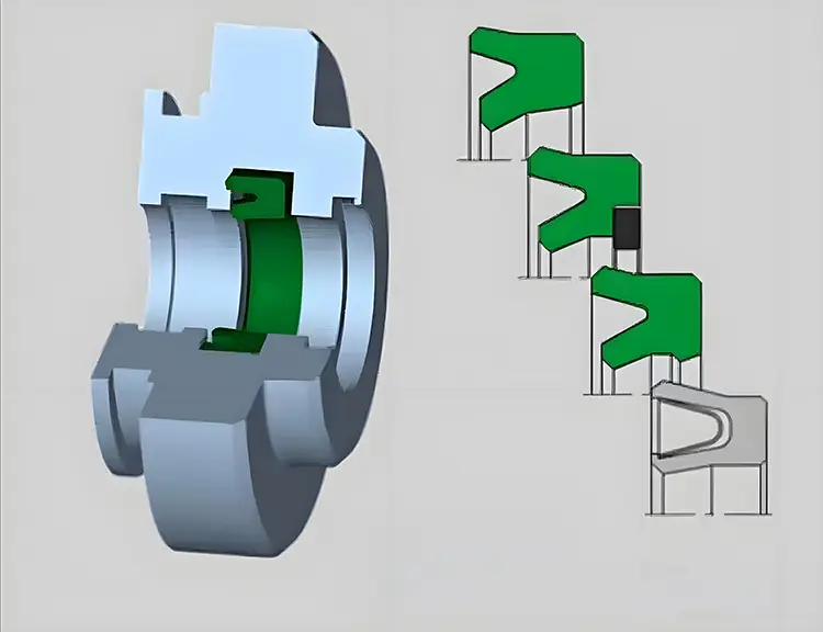
12.2 Hybrid Seal Designs
12.2.1 Metal-Elastomer Hybrids
Hybrid seals combine the elastic compliance of elastomers with the low permeation of metal shells or inserts.
- Common in analytical and industrial systems where low leakage and reusability are both required.
- Metal-encapsulated O-rings (e.g., stainless steel jacket with FKM core) are a practical bridge between elastomer and full-metal sealing.
12.2.2 Multi-Stage Sealing
Advanced vacuum pumps and rotating equipment increasingly use multi-stage sealing to optimize performance:
- Primary seal (e.g., dry gas or mechanical)
- Secondary buffer (e.g., labyrinth or purge seal)
- Tertiary containment or venting stage
This layered architecture improves operational safety, allows controlled leakage management, and extends service intervals.
12.3 Magnetic Fluid (Ferrofluidic) Seal Advancements
Traditional ferrofluidic seals are already renowned for their low leakage and long service life. Recent innovations have further expanded their performance envelope:
- High-temperature ferrofluids stable up to 200 °C.
- Radiation-resistant fluids for nuclear and space applications.
- Improved magnet geometries that minimize shear heating and extend lifetime.
- Multi-stage magnetic seals capable of withstanding higher pressure differentials.
These advances are particularly valuable in semiconductor manufacturing, UHV research, and space technology.
12.4 Smart Monitoring and Predictive Diagnostics
12.4.1 Sensor Integration
Modern vacuum systems increasingly integrate inline sensors near critical sealing interfaces:
- Temperature probes (RTDs or thermocouples).
- Vibration accelerometers.
- Differential pressure sensors across seals.
- Helium leak detectors or residual gas analyzers (RGA).
12.4.2 Predictive Algorithms
By logging operational data continuously and applying predictive algorithms (e.g., machine learning models), operators can:
- Detect early signs of seal degradation.
- Forecast remaining service life.
- Schedule maintenance only when necessary, avoiding premature replacements.
This approach is especially beneficial for high-value UHV tools, where unplanned downtime is extremely costly.
12.5 Sustainable Sealing Technologies
Sustainability is an emerging consideration in vacuum system design. Trends include:
- Longer-life seals (e.g., dry gas, magnetic fluid) to reduce waste and maintenance frequency.
- Recyclable or reusable metal seals, replacing single-use copper gaskets in some applications.
- Development of low-VOC, low-outgassing materials to meet environmental and cleanroom regulations.
- Reducing energy consumption through low-friction coatings and textures.
12.6 Additive Manufacturing of Seal Components
The advent of additive manufacturing (AM) is transforming how sealing hardware is designed:
- Custom metal flange geometries can be produced with optimized weight and thermal expansion characteristics.
- Integrated cooling or heating channels can be built directly into flanges to improve temperature control.
- AM allows rapid prototyping of non-standard sealing interfaces for research and aerospace.
While AM is still in early adoption for vacuum sealing, its potential is vast, particularly for complex, one-off research tools.
12.7 Emerging Materials
Research and commercial development are advancing new classes of sealing materials:
- Perfluoroelastomers with ultra-low permeation for harsh chemical and high vacuum environments.
- High-temperature polymer composites that maintain integrity beyond 300 °C.
- Advanced metallic alloys and surface-treated copper to reduce creep and improve reusability.
- Graphene and nanocarbon coatings for ultra-low friction and enhanced chemical resistance.
These innovations aim to combine the flexibility of elastomers, the inertness of PTFE, and the robustness of metals.
12.8 Summary
Modern sealing technology is moving toward higher performance, longer life, and smarter operation. Key trends include:
- Advanced coatings and surface engineering to minimize wear and contamination.
- Hybrid and multi-stage seals that combine different technologies for optimized performance.
- Smart monitoring systems enabling predictive maintenance.
- Sustainability and additive manufacturing opening new design pathways.
- Emerging materials pushing temperature, chemical, and vacuum boundaries further than before.
13. Worked Case Studies
While theory provides the framework, real-world case studies demonstrate how different sealing technologies and strategies perform under actual operating conditions. The following examples illustrate how proper seal selection, installation, and maintenance directly impact vacuum system performance, reliability, and cost of ownership.
We will examine three representative scenarios:
- UHV Viewport Retrofit — upgrading from elastomer to metal seals.
- Corrosive Process Shaft Sealing — hybrid dynamic sealing with purge.
- Hygienic Line Sealing — material selection for steam-in-place sterilization.
13.1 Case Study 1: UHV Viewport Retrofit
13.1.1 Background
A research laboratory operating a surface analysis system (XPS) was experiencing:
- Gradual base pressure drift from 1 × 10⁻⁹ Pa to 1 × 10⁻⁷ Pa.
- Extended pump-down times.
- Rising helium background during leak checks.
Initial inspection found that elastomer O-rings were used to seal several viewports. Over time, the elastomers had:
- Hardened due to bake-out cycles.
- Developed micro-cracks.
- Allowed helium permeation at measurable rates.
13.1.2 Retrofit Solution
The lab retrofitted the viewport assemblies using:
- CF flanges with OFHC copper gaskets (single-use).
- Knife-edge sealing surfaces machined to UHV tolerance.
- Tightened to manufacturer-recommended torque with cross-pattern sequence.
A helium leak test after installation showed leak rates below 1 × 10⁻¹¹ Pa·m³/s.
13.1.3 Results
| Parameter | Before Retrofit | After Retrofit |
|---|---|---|
| Base pressure | 1 × 10⁻⁷ Pa | 3 × 10⁻¹⁰ Pa |
| Pump-down time (to spec) | 4.5 hours | 2.2 hours |
| Helium leak rate (per viewport) | 1 × 10⁻⁸ Pa·m³/s | < 1 × 10⁻¹¹ Pa·m³/s |
| Seal replacement interval | ~6 months | > 3 years |
13.1.4 Lessons Learned
- Replacing elastomers with metal gaskets can dramatically reduce permeation and outgassing in UHV applications.
- Proper torque and surface preparation are critical to achieving leak rates in the 10⁻¹¹ Pa·m³/s range.
- Though metal seals cost more upfront, longer service intervals lower total cost of ownership.
13.2 Case Study 2: Corrosive Process Shaft Sealing
13.2.1 Background
A chemical plant operating a vacuum distillation unit with corrosive solvent vapors experienced:
- Frequent mechanical seal failures on a rotating shaft.
- Shaft corrosion near the seal interface.
- Contaminant ingress into the vacuum system.
Root cause analysis identified:
- Incompatible elastomers being attacked by chemical vapors.
- Insufficient barrier gas pressure in the dry gas seal system.
13.2.2 Retrofit Solution
A hybrid sealing solution was implemented:
- SiC vs. graphite mechanical seal faces for improved chemical resistance.
- FFKM secondary seals to handle aggressive solvent vapors.
- Dry nitrogen barrier gas with pressure control, creating a positive seal environment.
- Shaft material upgraded to Hastelloy® for corrosion resistance.
13.2.3 Results
| Parameter | Before Retrofit | After Retrofit |
|---|---|---|
| Mean time between failures (MTBF) | 6 months | 4+ years (still in service) |
| Helium leak rate | 1 × 10⁻⁶ Pa·m³/s | < 1 × 10⁻⁸ Pa·m³/s |
| Seal replacement cost | High (frequent) | Moderate (infrequent) |
| Product contamination events | 4/year | 0/year |
13.2.4 Lessons Learned
- Hybrid seal designs with barrier gas systems can greatly improve reliability in corrosive environments.
- Material upgrades (FFKM, SiC) provide both chemical compatibility and longer service life.
- Purge systems must be carefully controlled to maintain stable pressure differentials.
13.3 Case Study 3: Hygienic Line Sealing in Biopharma
13.3.1 Background
A biopharmaceutical production facility used EPDM gaskets in Tri-Clamp hygienic connections throughout a lyophilization system. After repeated SIP (steam-in-place) cycles:
- Gaskets became brittle and cracked.
- Microleaks were detected during integrity testing.
- Downtime increased due to frequent gasket replacement.
13.3.2 Retrofit Solution
The plant evaluated alternative materials and adopted:
- PTFE gaskets for steam exposure areas.
- Platinum-cured silicone gaskets for low-temperature service.
- Strict torque procedures and visual inspections between SIP cycles.
- A scheduled replacement interval based on validation testing rather than reactive failures.
13.3.3 Results
| Parameter | Before Retrofit | After Retrofit |
|---|---|---|
| Leak incidents/year | 8 | 0 |
| Mean service life per gasket | 2 months | 12 months |
| Maintenance time per shutdown | 6 hours | 2 hours |
| Regulatory deviations logged | 3 | 0 |
13.3.4 Lessons Learned
- Regulatory-driven industries benefit from proactive, validated material selection.
- PTFE and silicone can provide longer service life in steam sterilization environments.
- Proper torque control and inspection protocols reduce unplanned maintenance.
13.4 Cross-Case Insights
Across these case studies, several common principles emerge:
- Material selection aligned with application environment (e.g., copper for UHV, FFKM for chemical resistance, PTFE for sterilization).
- Hybrid and upgraded seal designs significantly extend service life.
- Torque control, alignment, and cleanliness are just as important as seal type.
- Monitoring and scheduled maintenance turn reactive fixes into predictable operations.
- Total cost of ownership often favors higher-performance seals over cheaper, short-life alternatives.
13.5 Summary
| Case Study | Challenge | Solution Highlights | Result |
|---|---|---|---|
| UHV Viewport Retrofit | Permeation & outgassing of elastomers | CF flanges + copper gaskets | Lower base pressure, longer service life |
| Corrosive Process Shaft Sealing | Seal failure in chemical exposure | SiC/graphite faces, FFKM, barrier gas | Extended MTBF, reduced contamination |
| Hygienic Line Sealing | Gasket degradation in SIP cycles | PTFE + silicone gaskets, torque control | Regulatory compliance, zero leak failures |
These examples illustrate how tailored sealing strategies deliver measurable performance improvements in diverse vacuum applications.
14. Practical Tools
Vacuum sealing involves numerous variables — from vacuum class and material compatibility to torque control and maintenance schedules. To help engineers apply the concepts covered throughout this guide, this chapter provides practical engineering tools including decision trees, compatibility tables, and standardized checklists.
These tools are designed to support consistent, repeatable, and efficient engineering practices, whether for system design, installation, operation, or maintenance.
14.1 Seal Selection Decision Tree
A structured decision tree simplifies the process of selecting the correct seal type for any vacuum application.
1. Define interface type:
   ├── Static (go to 2)
   └── Dynamic (go to 5)

2. Determine required vacuum level:
   ├── Rough / High (go to 3)
   └── UHV / Extreme (go to 4)

3. Material selection for static seals:
   ├── Chemical compatibility moderate → FKM / EPDM O-rings
   ├── Chemical compatibility aggressive → PTFE or FFKM
   └── Bake-out requirement high → Metal gasket (CF)

4. UHV sealing:
   ├── Bake-out < 400 °C → OFHC copper gasket (CF flange)
   └── Bake-out > 400 °C or permanent → Welded or brazed joint

5. Dynamic sealing:
   ├── Low speed → Packing, mechanical seal, lip seal
   ├── High speed / Clean process → Dry gas seal, ferrofluidic seal
   └── Rough vacuum only → Lip seals acceptable

6. Final considerations:
   ├── Maintenance interval short → Elastomer or soft gasket acceptable
   ├── Maintenance interval long → Metal or advanced non-contact seals
   ├── Contamination-sensitive → Prefer non-contact or metal seals
This tree provides a first-pass selection, to be refined with detailed engineering review.
14.2 Quick Material Compatibility Table
| Material | Max Temp (°C) | Permeation | Outgassing | Chemical Resistance | Bake-Out | Typical Use |
|---|---|---|---|---|---|---|
| NBR | 120 | High | High | Poor–Moderate | No | Rough vacuum, general utility |
| EPDM | 150 | Moderate | Moderate | Good (steam) | No | Industrial, water vapor, HVAC |
| FKM (Viton®) | 200 | Low | Low | Excellent | Limited | High vacuum, chemical process |
| FFKM | 280 | Very Low | Very Low | Outstanding | Limited | Semiconductor, corrosive media |
| PTFE | 250 | Very Low | Very Low | Excellent | Yes | Gaskets, envelope seals |
| PCTFE | 150 | Very Low | Very Low | Excellent | Yes | Cryogenic, UHV |
| PEEK | 250 | Very Low | Low | Excellent | Yes | High-strength, structural seals |
| Copper | 450+ | None | None | Excellent | Yes | CF flanges, UHV |
| Nickel alloys | 450+ | None | None | Excellent | Yes | Corrosive, high-temp |
| Ferrofluid | ~200 | Very Low | Very Low | Good (depends) | No | Dynamic rotary sealing, UHV |
14.3 Installation Checklist (Static Seals)
| Step | Action | Notes |
|---|---|---|
| 1 | Clean sealing surfaces with solvent and lint-free wipes | No fingerprints, oil, or debris |
| 2 | Inspect for scratches, dents, or misalignment | Use bright lighting or magnification |
| 3 | Verify seal material and size | Check compatibility with process media and temperature |
| 4 | Lightly lubricate elastomer (if required) with vacuum-compatible lubricant | Avoid hydrocarbons |
| 5 | Install seal without twisting or stretching | Use alignment pins if necessary |
| 6 | Torque bolts in a cross-pattern in gradual increments | Calibrated torque wrench recommended |
| 7 | Perform helium leak test or pressure rise test | Target leak rate appropriate to vacuum class |
| 8 | Record installation data (torque, date, leak rate) | Enables trend analysis and predictive maintenance |
14.4 Installation Checklist (Dynamic Seals)
| Step | Action | Notes |
|---|---|---|
| 1 | Verify shaft alignment and concentricity | Misalignment causes premature wear |
| 2 | Inspect seal faces (mechanical/dry gas) for flatness and cleanliness | Critical for low leakage |
| 3 | Install secondary seals (O-rings, bellows) without damage | Ensure proper groove seating |
| 4 | Set spring load or hydraulic pressure according to manufacturer specifications | Over-compression leads to overheating |
| 5 | Connect and purge barrier gas systems (if applicable) | Dry nitrogen or clean process gas |
| 6 | Rotate shaft manually to check for smooth operation | No abnormal drag or resistance |
| 7 | Leak test assembled system | Record baseline data |
14.5 Leak Testing Acceptance Criteria
| Vacuum Level | Typical Acceptance Limit | Typical Test Method |
|---|---|---|
| Rough vacuum | ≤ 1 × 10⁻⁵ Pa·m³/s | Pressure rise, bubble test |
| High vacuum | ≤ 1 × 10⁻⁸ Pa·m³/s | Helium sniffing or vacuum mode |
| UHV | ≤ 1 × 10⁻¹⁰ Pa·m³/s | Helium leak detection (high sensitivity) |
| Extreme / UHV+ | < 1 × 10⁻¹¹ Pa·m³/s | Helium leak detection, RGA verification |
Note: Acceptance limits may be tightened based on process contamination sensitivity, e.g., semiconductor or space applications.
14.6 Maintenance Interval Reference Table
| Seal Type | Typical Service Interval | Maintenance Focus |
|---|---|---|
| O-rings (NBR, EPDM) | 6–12 months | Replace on schedule, check compression set |
| O-rings (FKM, FFKM) | 1–3 years | Monitor for permeation, bake-out stability |
| Soft PTFE gaskets | 1–2 years | Check for creep and cold flow |
| Metal gaskets (CF) | 3–5+ years | Torque check post-bake |
| Mechanical seals | 2–5 years | Face wear, alignment |
| Dry gas seals | 3–10 years | Barrier gas quality, groove condition |
| Ferrofluidic seals | 5–15 years | Ferrofluid integrity, magnet performance |
14.7 Torque Guidelines (Typical)
| Flange Type | Gasket Material | Typical Torque per Bolt | Notes |
|---|---|---|---|
| KF (small) | Elastomer | 8–12 N·m | Uniform hand tightening acceptable |
| ISO-K | Elastomer/PTFE | 15–30 N·m | Cross-pattern recommended |
| CF (DN63–DN200) | Copper | 25–40 N·m | Must follow manufacturer’s values |
| Large CF flanges | Copper | 40–70 N·m | Use calibrated torque wrench |
| Helicoflex | Metal C-ring | Per manufacturer | Controlled compression critical |
These values are indicative; always confirm with manufacturer specifications for the specific flange and gasket.
14.8 Maintenance and Inspection Log Template
| Date | System | Seal Type | Material | Torque (N·m) | Leak Rate (Pa·m³/s) | Observations | Action Taken | Next Due |
|---|---|---|---|---|---|---|---|---|
| 2025-05-14 | Main chamber | CF flange | Copper | 35 | 5 × 10⁻¹² | OK | — | 2028-05 |
| 2025-05-15 | Rotary shaft | Dry gas seal | SiC/Graphite | — | 2 × 10⁻⁹ | Stable temperature | — | 2029-05 |
| 2025-05-20 | Diagnostic port | O-ring | FKM | 15 | 3 × 10⁻⁸ | Slight wear | Replaced O-ring | 2026-05 |
This standardized format allows trend tracking, early anomaly detection, and easy handover between maintenance teams.
14.9 Process Control Checklists
Pre-Startup
- Leak test passed within specification.
- All torque values logged.
- Barrier gas supply pressure verified.
- Temperature sensors operational.
- Flange alignment and cleanliness confirmed.
Routine Operation
- Base pressure within target range.
- Pump-down time consistent.
- Seal temperature stable.
- No abnormal vibration or noise.
- Helium leak rate trend normal.
Shutdown
- Inspect seals visually.
- Log torque and leak data.
- Clean sealing surfaces if system will remain idle.
- Cover open flanges to prevent contamination.
14.10 Summary
Practical tools like decision trees, checklists, and compatibility tables help:
- Standardize engineering workflows.
- Minimize installation and maintenance errors.
- Support predictive maintenance programs.
- Ensure consistent sealing performance across different systems.
With these tools in hand, sealing performance becomes more repeatable, traceable, and efficient.
15. Glossary & Unit Conversions
A clear understanding of technical terms and unit conventions is essential for communicating and applying vacuum sealing knowledge effectively. This chapter provides a glossary of key concepts and a reference table of unit conversions commonly used in vacuum technology and sealing engineering.
15.1 Glossary of Key Terms
A
- Absolute Pressure — Pressure measured relative to a perfect vacuum (0 Pa). In vacuum technology, all pressure values are typically expressed as absolute pressure.
- All-Metal Seal — A seal constructed entirely of metal, such as copper or nickel, used primarily in UHV applications to eliminate permeation and minimize outgassing.
- ANSI / ISO Flange — Standardized flange geometries used for vacuum piping and chamber connections.
B
- Bake-Out — The process of heating vacuum components to desorb volatile molecules from surfaces and reduce outgassing. Typically performed at 150–450 °C.
- Base Pressure — The lowest pressure a vacuum system can achieve under defined conditions, typically after bake-out and stabilization.
- Barrier Gas — A clean gas (often nitrogen) introduced between sealing stages to protect seals from process contamination or to reduce leakage.
C
- CF Flange (ConFlat®) — A UHV flange standard that uses a knife-edge and copper gasket to achieve extremely low leak rates. Widely used in scientific and semiconductor applications.
- Compression Set — The permanent deformation of an elastomer after prolonged compression, reducing its ability to maintain a seal.
- Contact Seal — A sealing technology where two surfaces are in direct mechanical contact, such as mechanical seal faces or O-ring interfaces.
D
- Differential Pumping — Technique where an intermediate volume between seals is pumped to maintain vacuum integrity and minimize leakage from one stage to another.
- Dry Gas Seal — A non-contacting mechanical seal that uses gas film lubrication to reduce leakage and wear, common in high-speed rotating equipment.
E
- Elastomer — A class of flexible, rubber-like materials used in O-rings and soft gaskets. Examples include NBR, EPDM, FKM, and FFKM.
- Envelope Gasket — A gasket with a PTFE outer layer and an elastomer core, combining chemical resistance with elastic sealing force.
F
- Ferrofluidic Seal — A non-contact rotary seal that uses a magnetic fluid held in place by a magnetic field to block gas flow, achieving very low leakage in UHV.
- Flange Flatness — Deviation of the flange sealing surface from a perfectly flat plane. High flatness is critical for metal seals.
G
- Gas Permeation — The process by which gas molecules diffuse through a sealing material, a key limitation of elastomers in high vacuum.
- Gland — The groove or housing in which an O-ring or other seal is installed.
H
- Helium Leak Detection — Standard method of detecting leaks in vacuum systems using helium tracer gas and a mass spectrometer-based leak detector.
- Helicoflex® Seal — A reusable metallic C-ring or spring-energized seal with extremely low leak rates, often used in high-temperature or UHV systems.
L
- Labyrinth Seal — A non-contact seal that uses a tortuous path to reduce leakage, often used with buffer gases.
- Leak Rate — The volumetric flow of gas through a leak, typically expressed in Pa·m³/s or mbar·L/s.
M
- Mechanical Seal — A type of dynamic seal that uses two lapped faces in sliding contact to prevent leakage along a rotating shaft.
- Metal Gasket — A gasket made of metal (e.g., OFHC copper) used for static sealing in UHV systems.
O
- O-Ring — A circular elastomeric seal with an O-shaped cross-section, widely used in static and moderate vacuum applications.
- Outgassing — The release of adsorbed or trapped gases and vapors from materials under vacuum, which can degrade vacuum quality.
P
- Packing Seal — A traditional sealing method using compressible packing in a stuffing box, common in valves and low-speed rotary equipment.
- Permeation — The diffusion of gas through a material. For vacuum sealing, permeation through elastomers is often a dominant gas load.
R
- Residual Gas Analyzer (RGA) — Instrument used to monitor gas composition in a vacuum system, often for detecting leaks or contamination.
- Rough Vacuum — Pressure range typically from atmospheric pressure down to about 100 Pa.
S
- Seal Compression — The deformation of a sealing element to create contact pressure that prevents leakage.
- Soft Gasket — A gasket made of deformable non-metallic material such as PTFE, graphite, or elastomer.
- Spiral Groove Seal — A dry gas seal design that uses spiral grooves to generate a gas film between seal faces.
T
- Torque Pattern — The sequence in which flange bolts are tightened to ensure even compression of the seal.
- Total Cost of Ownership (TCO) — The overall cost associated with a seal over its service life, including installation, maintenance, and downtime.
U
- Ultra-High Vacuum (UHV) — Pressure range below 1 × 10⁻⁷ Pa, where even minute leaks or outgassing can affect performance.
- UHV-Compatible Seal — Sealing technology that maintains ultra-low leakage under bake-out and extended operation, typically all-metal.
V
- Vacuum-Compatible Lubricant — Special lubricant with extremely low vapor pressure, used to prevent O-ring twisting without contaminating vacuum.
- Virtual Leak — A trapped volume that slowly releases gas, mimicking a real leak during pump-down.
15.2 Common Unit Conversions
15.2.1 Pressure
| Unit | Pa (SI) | Torr | mbar | atm |
|---|---|---|---|---|
| 1 Pa | 1 | 7.5 × 10⁻³ Torr | 0.01 mbar | 9.87 × 10⁻⁶ atm |
| 1 Torr | 133.322 Pa | 1 | 1.333 mbar | 1.315 × 10⁻³ atm |
| 1 mbar | 100 Pa | 0.75 Torr | 1 | 9.87 × 10⁻⁴ atm |
| 1 atm | 101,325 Pa | 760 Torr | 1,013.25 mbar | 1 |
15.2.2 Leak Rate
Leak rate is commonly expressed in Pa·m³/s or mbar·L/s.
| Unit | Conversion |
|---|---|
| 1 Pa·m³/s | 10 mbar·L/s |
| 1 mbar·L/s | 0.1 Pa·m³/s |
15.2.3 Torque
| Unit | Conversion |
|---|---|
| 1 N·m | 8.85 in·lbf |
| 1 in·lbf | 0.113 N·m |
15.2.4 Temperature
| Unit | Conversion |
|---|---|
| °C to K | K = °C + 273.15 |
| K to °C | °C = K − 273.15 |
| °C to °F | °F = (°C × 9/5) + 32 |
| °F to °C | °C = (°F − 32) × 5/9 |
15.3 Common Abbreviations
| Abbreviation | Meaning |
|---|---|
| CF | ConFlat flange |
| CIP | Clean-In-Place |
| DLC | Diamond-Like Carbon |
| EPDM | Ethylene Propylene Diene Monomer |
| FDA | U.S. Food and Drug Administration |
| FFKM | Perfluoroelastomer |
| FKM | Fluoroelastomer |
| KF | Klein Flange (Quick flange standard) |
| MTBF | Mean Time Between Failures |
| NBR | Nitrile Butadiene Rubber |
| OFHC | Oxygen-Free High Conductivity (copper) |
| PTFE | Polytetrafluoroethylene |
| RGA | Residual Gas Analyzer |
| SIP | Steam-In-Place |
| TCO | Total Cost of Ownership |
| UHV | Ultra-High Vacuum |
| USP | United States Pharmacopeia |
15.4 Reference Leak Rates
| System Class | Typical Leak Rate Requirement | Typical Seal Type |
|---|---|---|
| Rough vacuum | ≤ 1 × 10⁻⁵ Pa·m³/s | Elastomer O-rings, soft gaskets |
| High vacuum | ≤ 1 × 10⁻⁸ Pa·m³/s | FKM/FFKM, PTFE gaskets, mechanical seals |
| Ultra-high vacuum | ≤ 1 × 10⁻¹⁰ Pa·m³/s | Copper gaskets, Helicoflex®, welded |
| Extreme / cryogenic | < 1 × 10⁻¹¹ Pa·m³/s | All-metal, welded, magnetic seals |
15.5 Summary
This glossary and conversion reference provide a quick technical resource for:
- Clarifying specialized terminology.
- Ensuring correct unit usage in design and maintenance documentation.
- Enabling clear communication between design, operations, and maintenance teams.
- Supporting accurate calculations in leak testing, torque control, and vacuum design.
16. Conclusion & Best Practices Summary
Vacuum sealing is far more than a mechanical detail — it is a core enabler of vacuum system performance, directly affecting achievable pressure, contamination levels, process stability, and maintenance costs. Over the previous chapters, we’ve explored this topic from fundamental physics to advanced sealing technologies. This concluding chapter distills those lessons into a strategic overview of best practices that engineers can apply across a wide range of industries and vacuum environments.
16.1 The Strategic Role of Sealing in Vacuum Systems
Seals determine:
- The tightness of the vacuum boundary.
- The cleanliness of the process environment.
- The efficiency of pump-down and base pressure stability.
- The lifecycle cost of operating the system.
Poor sealing choices lead to:
- Unpredictable leaks and contamination events.
- Increased pump loads and energy consumption.
- Frequent maintenance shutdowns.
- Product quality issues in critical processes.
Conversely, well-engineered sealing strategies allow systems to run longer, cleaner, and more efficiently with lower overall costs.
16.2 Key Takeaways by Lifecycle Stage
16.2.1 Design & Selection
- Start with accurate definition of operating conditions: vacuum level, media, temperature, motion, and maintenance strategy.
- Select materials that balance permeation resistance, chemical compatibility, and mechanical durability.
- Use structured tools like decision trees and compatibility tables to standardize selection.
- Design for serviceability — consider access, replacement intervals, and inspection procedures early.
16.2.2 Installation & Commissioning
- Precision in surface finish, alignment, and torque application is non-negotiable.
- Perform helium leak testing and baseline data logging during installation.
- Apply controlled pump-down procedures to avoid stress on seals.
- Use clean assembly practices to minimize outgassing.
16.2.3 Operation & Monitoring
- Monitor temperature, vibration, and leak rates over time.
- Detect early signs of degradation through trend analysis, not just threshold alarms.
- Apply predictive maintenance for critical seals.
- Keep clear, standardized operational logs.
16.2.4 Maintenance & Lifecycle Management
- Implement a hybrid preventive + predictive maintenance approach.
- Manage seal inventories with proper storage and shelf-life tracking.
- Conduct root cause analysis on failures to continuously improve reliability.
- Use total cost of ownership (TCO) as a metric when comparing seal technologies.
16.3 Technological Trends to Watch
- Advanced coatings such as DLC are increasing the life of dynamic seals.
- Hybrid and multi-stage sealing architectures are becoming standard in high-performance systems.
- Smart sensors and predictive algorithms are turning sealing from a passive element into an actively monitored component.
- Sustainable sealing technologies are reducing waste, energy use, and maintenance frequency.
- Additive manufacturing enables more sophisticated and integrated sealing solutions.
These trends point to a future where vacuum sealing systems are smarter, more efficient, and more durable.
16.4 Industry Adaptation
Each industry adapts sealing strategies according to its priorities:
| Sector | Primary Concern | Key Sealing Approach |
|---|---|---|
| Semiconductor / UHV | Cleanliness, leakage control | Metal seals, ferrofluidic, welded joints |
| Chemical Processing | Corrosion resistance | FFKM, PTFE, hybrid dynamic seals with purge |
| Pharma & Food | Hygiene, compliance | EPDM, PTFE, validated elastomers |
| Energy & Vacuum Furnaces | High temperature | Metal gaskets, Helicoflex, retorque protocols |
| Research & Analytical | Flexibility, modularity | CF flanges, KF elastomers, hybrid seals |
The principles are universal, but the implementation is context-specific.
16.5 Best Practice Checklist
Design
- Define all environmental and operational parameters.
- Match seal type to vacuum class and contamination tolerance.
- Minimize dynamic sealing wherever possible.
- Incorporate serviceability into design.
Installation
- Clean surfaces meticulously.
- Control torque and flange alignment.
- Verify seal placement and condition.
- Perform helium leak test and log results.
Operation
- Monitor pressure, temperature, and vibration trends.
- Track seal performance over time.
- Keep barrier gas systems stable and clean.
- Maintain operational cleanliness.
Maintenance
- Schedule preventive replacement for elastomers.
- Apply predictive techniques for critical seals.
- Document maintenance actions and leak rates.
- Conduct failure analysis to improve future reliability.
16.6 Final Thoughts
Vacuum sealing may appear secondary to pumps, valves, or chambers — but in reality, it is the foundation upon which all other performance depends. An excellent vacuum seal:
- Eliminates unpredictable process interruptions.
- Supports higher vacuum performance with less pumping effort.
- Enables longer system uptime and lower maintenance costs.
- Enhances safety, product quality, and regulatory compliance.
By applying the principles and tools detailed in this guide — from material selection to predictive monitoring — you can achieve stable, efficient, and sustainable vacuum sealing performance.