
1. Introduction
In reciprocating sealing systems, the performance of an elastomeric seal is determined by more than just its material properties. While choosing the right elastomer is essential, the geometry of the groove and the quality of the sealing surface play an equally critical role in ensuring reliable sealing performance and long service life.
A well-designed groove provides proper support and compression to the seal, maintaining a stable sealing line under varying pressures and temperatures. Meanwhile, surface finish and tolerance control ensure minimal friction, reduced wear, and consistent lubrication — all of which are vital in dynamic sealing applications such as hydraulic cylinders, pneumatic actuators, and process equipment.
Poorly designed grooves or rough surfaces often lead to premature seal failure, including extrusion, spiral failure, tearing, or leakage. These issues not only compromise system performance but can also lead to costly downtime. Therefore, understanding and applying sound groove and surface design principles is fundamental to achieving a robust and efficient reciprocating sealing system.
In the following sections, we will explore the core principles of groove geometry, surface finish, lubrication, installation considerations, common mistakes, and practical design recommendations.
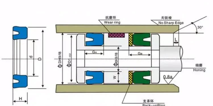
2. Groove Geometry Fundamentals
The groove is the foundation of any reciprocating sealing system. Its design directly affects how the seal is compressed, supported, and stabilized during operation. A well-proportioned groove prevents seal displacement, extrusion, and uneven wear — all of which can shorten service life or cause leakage.
2.1 Groove Depth
Groove depth determines the squeeze ratio between the seal and the mating surface. If the groove is too shallow, the seal may be over-compressed, increasing friction, heat buildup, and wear. If the groove is too deep, the seal may not make sufficient contact, leading to leakage.
- Typical squeeze ratio: 10–20% for most elastomeric seals in reciprocating applications.
- Always account for thermal expansion and pressure deformation when finalizing depth.
2.2 Groove Width
The groove must provide enough lateral space for the seal to expand under pressure without becoming unstable. A width that’s too narrow can cause seal extrusion or edge loading; too wide, and the seal may roll or twist.
- Guideline: Groove width should generally be 1.1–1.3 times the seal cross-section.
2.3 Bottom Radius and Corner Design
Sharp corners at the bottom of a groove create stress concentrations, which can cut or tear the seal during installation or operation. A small fillet radius at the groove bottom helps distribute stress more evenly.
- Recommendation: Apply a fillet radius typically between 0.2–0.5 mm, depending on the seal size.
2.4 Clearance and Extrusion Gap
In high-pressure applications, the gap between the groove and mating surface must be carefully controlled to prevent extrusion of the elastomer into the clearance. Backup rings may be added for additional support.
- Extrusion gap limit: Usually less than 0.2 mm for pressures above 10 MPa.
2.5 Pressure and Stroke Considerations
Operating pressure and stroke length significantly affect groove design. Higher pressures require tighter clearance and possibly back-up elements, while longer strokes demand greater stability to avoid twisting or rolling of the seal.
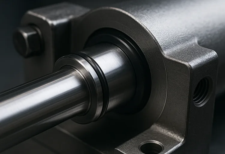
3. Surface Finish and Tolerance Requirements
The surface finish of the rod and bore is a critical factor in the performance of elastomeric reciprocating seals. Even if the groove geometry is perfect, a poorly finished surface can lead to rapid wear, lubrication failure, or leakage. In contrast, a well-controlled surface allows the seal to glide smoothly with minimal friction and consistent sealing pressure.
3.1 Importance of Surface Quality
When the sealing lip moves along the mating surface, it relies on a thin lubrication film to minimize friction and wear.
- If the surface is too rough, the peaks can cut or abrade the seal, resulting in leakage and premature failure.
- If the surface is too smooth, there may not be enough micro-valleys to retain lubricant, increasing the risk of dry friction and heat buildup.
3.2 Recommended Surface Roughness
For most dynamic sealing applications, Ra values between 0.2 and 0.4 μm are considered optimal. This provides the right balance between sealing effectiveness and lubrication retention.
Typical recommendations:
- Piston rods and plungers: Ra 0.2–0.4 μm
- Cylinder bores: Ra 0.3–0.6 μm
In some critical applications (e.g., high-speed hydraulics), Rz and other profile parameters may also be specified to ensure uniformity.
3.3 Concentricity, Roundness, and Straightness
Surface finish is only effective if the surface itself is dimensionally stable. Misalignment or uneven surfaces create localized pressure points that lead to accelerated seal wear.
- Concentricity should typically be held within 0.05 mm.
- Roundness and straightness should be maintained to avoid eccentric seal loading.
- Any form of taper or ovality should be minimized.
3.4 Surface Treatment and Coating
In some applications, surface treatments can enhance performance:
- Hard chrome plating or nitriding improves wear resistance.
- Special low-friction coatings reduce startup friction and stick-slip.
- Proper surface hardness also protects against scoring and galling.
3.5 The Connection Between Surface and Seal Life
A smooth, well-finished surface ensures stable lubrication, low friction, and even seal loading, resulting in longer service life and more predictable performance. For high-performance sealing systems, surface finish is just as crucial as material selection or groove geometry.
4. Friction and Lubrication Considerations
Lubrication is the lifeline of any dynamic sealing system. For elastomeric reciprocating seals, friction control depends heavily on how well the groove and mating surfaces are designed to maintain an appropriate lubrication film during both start-up and steady-state operation. Poor lubrication leads to stick-slip, heat buildup, accelerated wear, and ultimately, seal failure.
4.1 The Role of Lubrication Film
When the piston or rod moves, a microfilm of lubricant should remain between the seal and the surface.
- This film minimizes direct contact and reduces wear.
- It also helps lower startup friction, which is often the most damaging phase of the motion cycle.
- A stable film allows smoother movement and less energy loss.
However, if the groove is too tight or the surface too smooth, the lubricant can be wiped away entirely, resulting in dry running conditions.
4.2 Groove Design and Lubrication
Proper groove geometry encourages controlled lubricant flow:
- Slight chamfers or relief grooves can be used to distribute lubricant more evenly.
- Axial grooves or micro-notches are sometimes applied in low-speed systems to assist in oil retention.
- Avoid excessive squeeze that blocks lubricant migration.
4.3 Minimizing Stick-Slip and Friction Spikes
Stick-slip is a common problem in reciprocating applications, especially at low speeds or low pressures. It occurs when static friction exceeds dynamic friction, causing jerky, uneven movement.
To reduce stick-slip:
- Use a surface finish with proper roughness (Ra 0.2–0.4 μm).
- Choose elastomers with good low-friction characteristics or use coatings.
- Ensure proper initial lubrication during installation.
4.4 Pressure Venting and Fluid Control
In double-acting sealing systems or long-stroke designs, pressure buildup between seals can cause instability or blow-by.
- Venting grooves or pressure relief holes can be added to equalize trapped pressure.
- Controlled venting also prevents the seal from ballooning or twisting.
4.5 Lubrication Medium Selection
The lubricant used must be compatible with the elastomer and the application conditions:
- Mineral oils are common for hydraulic systems.
- Silicone or fluorinated lubricants are preferred for chemically aggressive or high-temperature environments.
- Grease may be used for low-speed or intermittent duty cycles.
4.6 Balancing Sealing and Lubrication
One of the biggest design challenges is maintaining a tight seal without wiping the lubricant away completely. This balance is achieved through:
- Correct groove dimensions.
- Controlled surface finish.
- Proper material-lubricant compatibility.
A well-lubricated interface ensures lower friction, reduced wear, and more stable sealing performance over the entire service life.
5. Installation and Assembly Factors
Even a perfectly engineered groove and surface finish can fail in real-world applications if installation and assembly are not carefully considered. Reciprocating seals are sensitive to edge conditions, assembly forces, and tolerance variations. A small error during installation can result in nicks, rolling, or uneven compression, which compromise sealing performance from day one.
5.1 Chamfer and Lead-In Angle Design
A well-designed chamfer ensures that the seal can be installed smoothly without catching on sharp edges.
- Chamfer angle: Typically 15°–30° is recommended for most elastomeric seals.
- The lead-in should be free of burrs, sharp corners, or machining marks.
- Generous chamfer lengths are especially important for larger diameter seals or seals with delicate lips.
5.2 Avoiding Seal Damage During Installation
Seals can be damaged by improper tools, excessive stretching, or forcing the component into place.
- Use installation tools with rounded edges and non-metallic materials to avoid cutting the seal.
- For tight tolerances, lubricate the seal and groove prior to installation.
- Heating the seal slightly (within material limits) can help with fitting without overstretching.
5.3 Tolerance Stack-Up and Thermal Expansion
When designing groove dimensions, it’s important to account for manufacturing tolerances of both the groove and mating components.
- Even small deviations can lead to over- or under-compression.
- High-temperature environments may cause components to expand at different rates, changing the squeeze ratio and clearance.
- Material expansion coefficients should be factored into the final design.
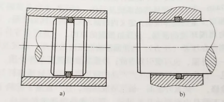
5.4 Single-Acting vs. Double-Acting Groove Designs
- Single-acting seals only face pressure from one side, so groove symmetry is less critical.
- Double-acting seals must handle pressure in both directions, requiring balanced grooves and precise centering to prevent twisting or extrusion.
- Pressure venting is often added in double-acting systems to stabilize performance.
5.5 Cleanliness and Surface Preparation
Before installation, ensure the groove and mating surfaces are clean, smooth, and free from debris. Any dirt or sharp machining remnants can damage the seal or create leak paths.
- Use lint-free cloths and approved cleaning agents.
- Inspect visually and with a finger check to detect hidden burrs.
5.6 Assembly Verification
After installation, a quick dimensional and functional check can help avoid failures:
- Verify correct seal positioning and seating.
- Ensure no twisting, folding, or uneven compression occurred.
- Run low-pressure tests before full system operation to confirm sealing integrity.
Proper installation isn’t just a final step — it’s a critical design consideration that should be planned from the very beginning. Thoughtful chamfering, tolerance control, and clean assembly conditions greatly reduce early failures and increase the seal’s working life.
6. Common Groove Design Mistakes
Even experienced engineers can overlook subtle but critical details in groove and surface design. These mistakes often lead to seal leakage, premature wear, or complete failure—sometimes within the first few operating cycles. Recognizing and avoiding these pitfalls is essential for building reliable reciprocating sealing systems.
6.1 Over-Compression or Under-Compression
One of the most common errors is specifying incorrect groove depth, which directly affects the seal squeeze ratio.
- Over-compression causes excessive friction, heat buildup, and rapid wear of the sealing lip.
- Under-compression leads to insufficient contact pressure, resulting in leakage.
- These issues often arise from not accounting for thermal expansion, tolerance variation, or material deformation.
Tip: Always calculate squeeze ratio carefully (typically 10–20% for elastomeric seals) and validate with real-world assembly conditions.
6.2 Sharp Edges and Burrs
Machined grooves sometimes have sharp edges or burrs, especially at the corners. These can:
- Cut the seal during installation.
- Create localized stress points.
- Accelerate cracking or tearing during operation.
Solution: Always apply a smooth fillet radius (0.2–0.5 mm) at the groove bottom and deburr all edges.
6.3 Poor Surface Finish
Neglecting surface roughness leads to direct consequences:
- Too rough → seal abrasion and early wear.
- Too smooth → lubricant starvation and stick-slip.
- Poor roundness or concentricity → uneven seal loading and leakage.
Solution: Specify Ra 0.2–0.4 μm for rods and Ra 0.3–0.6 μm for bores, with tight control on roundness and straightness.
6.4 Ignoring Extrusion Gaps
At higher operating pressures, elastomeric seals can be forced into gaps between components, leading to extrusion failure. This often occurs when the designer doesn’t account for pressure deformation or fails to include backup elements.
- Symptom: lip tearing, seal nibbling, or fragments in the fluid.
- Preventive measure: limit extrusion gaps (< 0.2 mm for high pressure) and use backup rings when needed.
6.5 Inadequate Lubrication Management
Many groove designs fail because lubrication wasn’t considered early in the design.
- Overly tight grooves wipe lubricant away.
- No relief paths lead to trapped pressure or uneven oil film.
- Dry running accelerates wear and failure.
Solution: Integrate relief chamfers, select appropriate surface finishes, and ensure proper lubricant compatibility with the elastomer.
6.6 Overlooking Assembly Conditions
Even if the groove design is theoretically correct, ignoring installation factors can undo all the work.
- No chamfers lead to damage during assembly.
- Poor cleanliness introduces debris under the seal.
- Unchecked tolerances result in unpredictable squeeze.
Solution: Treat assembly as part of the design process, not an afterthought.
7. Practical Design Examples and Recommendations
Designing grooves and surfaces for elastomeric reciprocating seals requires more than theoretical calculations — it demands practical, field-tested guidelines. In this section, we’ll walk through some typical design parameters, surface recommendations, and troubleshooting tips that engineers and buyers can apply directly to their projects.
7.1 Typical Groove Dimensions for Common Seals
Although the exact dimensions vary by seal type, material, and operating pressure, some general guidelines apply to most reciprocating applications:
| Seal Cross-Section (mm) | Groove Width (mm) | Groove Depth (mm) | Fillet Radius (mm) | Extrusion Gap (mm) |
|---|---|---|---|---|
| 3 | 3.5–4.0 | 2.6–2.8 | 0.2–0.3 | ≤ 0.15 |
| 5 | 5.5–6.5 | 4.3–4.5 | 0.3–0.5 | ≤ 0.20 |
| 8 | 9.0–10.0 | 7.0–7.3 | 0.5 | ≤ 0.25 |
- Groove width should provide enough space for the seal to expand without allowing rolling or twisting.
- Depth should create the correct squeeze ratio to balance sealing and friction.
- Fillet radius helps avoid stress concentrations at the groove corners.
Note: Always adjust dimensions based on material hardness, pressure, and thermal expansion characteristics.
7.2 Surface Roughness and Hardness
| Component | Recommended Ra (μm) | Typical Surface Treatment | Hardness (HRC) |
|---|---|---|---|
| Rod / Shaft | 0.2–0.4 | Hard chrome, nitriding | ≥ 50 |
| Bore / Cylinder | 0.3–0.6 | Honed steel, hard anodizing | ≥ 40 |
- Uniform roughness ensures stable lubrication and avoids stick-slip.
- Surface hardness protects against scoring and prolongs seal life.
- Surface treatment selection should consider the seal material’s compatibility with coatings.
7.3 Chamfer and Installation Details
- Chamfer angle: 15°–30° with a length at least equal to the seal cross-section.
- Deburring: Mandatory on all groove edges and lead-ins.
- Lubrication during installation: Prevents tearing and uneven seating.
7.4 Pressure Venting and Relief Design
- Include venting grooves or relief holes between multiple seals in double-acting systems.
- Prevent pressure trapping, which can push seals out of position or cause blow-by.
- Keep vent paths smooth and properly dimensioned to avoid turbulence or clogging.
7.5 Troubleshooting Common Failures
| Problem | Likely Cause | Recommended Action |
|---|---|---|
| Early wear / abrasion | Surface too rough, dry running | Improve surface finish, ensure lubrication |
| Seal extrusion | Excessive clearance, no backup ring | Reduce extrusion gap, add backup support |
| Leakage under pressure | Groove too deep, under-compression | Adjust groove depth, recheck tolerance stack-up |
| Spiral failure | Groove too wide, poor alignment | Reduce groove width, improve guidance system |
| Seal tearing during assembly | Sharp edges, no chamfer | Add chamfer, deburr edges, lubricate |
These examples reflect common real-world scenarios where small adjustments in geometry, surface quality, or installation lead to dramatic improvements in seal performance.
8. Conclusion
The performance and durability of elastomeric reciprocating seals depend on far more than the seal material alone. Groove and surface design form the structural foundation that determines whether a seal will operate smoothly for thousands of cycles — or fail prematurely after a few hours.
A well-designed groove provides proper support, squeeze, and stability, while a finely controlled surface finish ensures optimal lubrication and minimal friction. Careful consideration of chamfer angles, tolerance stack-ups, and installation practices further reduces the risk of early damage. Conversely, overlooking even a small detail — such as a sharp edge or excessive extrusion gap — can lead to leakage, wear, or catastrophic seal failure.
In practice, achieving reliable sealing requires:
- Balanced groove geometry that matches the seal’s cross-section and pressure conditions.
- Precision surface finishing to support a stable lubrication film.
- Thoughtful installation design, including chamfering and venting where needed.
- Rigorous inspection and tolerance control throughout the manufacturing process.
By integrating these design principles early in the engineering process, designers and maintenance teams can maximize seal life, reduce downtime, and ensure consistent system performance. Groove and surface design should never be treated as an afterthought — it’s a core part of a successful sealing strategy.