
1. Overview of Common Pump Sealing Methods
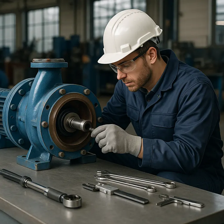
In industrial, agricultural, municipal, and chemical applications, pumps are indispensable for transporting fluids. However, one of the most persistent challenges in pump operation is preventing leakage.
A reliable sealing system is critical not only for maintaining system efficiency but also for avoiding environmental hazards, product losses, and safety risks.
Why Pump Sealing Matters
When a pump leaks:
- Operational efficiency drops due to fluid loss.
- Safety hazards increase, especially when handling hazardous or corrosive media.
- Environmental pollution can occur if chemicals or oils enter soil or waterways.
- Maintenance costs rise because seals require repair or replacement.
Therefore, understanding different sealing methods and their failure causes is essential for engineers, maintenance teams, and equipment buyers.
1.1 Common Pump Sealing Methods
Pumps typically use one or more of the following sealing types:
- Mechanical Seal – Uses two precision-engineered faces to prevent leakage. Offers high reliability for most industrial applications.
- O-ring Seal – Simple yet highly effective elastomer ring for static or dynamic sealing.
- Dynamic Seal / Auxiliary Impeller Seal – Uses an impeller to generate a pressure barrier during operation.
- Packing Seal – Utilizes braided or molded packing material compressed into a stuffing box.
- Labyrinth Seal – A non-contact design using a series of ridges and grooves to reduce leakage paths.
- Thread Seal – Relies on the mating of screw threads, often with a sealing compound or tape.
1.2 How to Select a Pump Sealing Method
Choosing the right seal depends on:
- Fluid characteristics: viscosity, temperature, corrosiveness, and presence of solids.
- Operating pressure: high-pressure applications may require double mechanical seals or special materials.
- Shaft speed: high RPM can generate heat and wear, requiring specific seal designs.
- Maintenance frequency: seals that are easier to replace reduce downtime.
- Cost considerations: balancing initial investment with long-term reliability.
1.3 Real-World Application Examples
- Chemical Processing Plants: Often use mechanical seals with corrosion-resistant materials to handle acids or solvents.
- Municipal Water Supply: O-ring or packing seals are common due to lower cost and ease of maintenance.
- Slurry Pumps in Mining: Prefer labyrinth seals or heavy-duty packing to handle abrasive particles.
- Oil & Gas Industry: Double mechanical seals with a pressurized barrier fluid are standard for hazardous media.
2. Mechanical Seal
2.1 Introduction
The mechanical seal is one of the most widely used shaft sealing methods in modern pumps. It works by pressing two precisely machined, flat sealing faces together—one rotating with the shaft and the other stationary in the pump casing.
A thin lubricating film exists between these faces, which reduces friction, minimizes wear, and creates a controlled leakage that is often so small it is practically undetectable.
Mechanical seals are preferred in many industries because they:
- Offer superior sealing performance compared to packing seals.
- Require less frequent maintenance when properly installed and operated.
- Reduce operational costs by minimizing fluid loss.
However, in real-world applications, achieving and maintaining optimal performance can be challenging due to various operational, installation, and design factors.
2.2 Common Leakage Causes in Mechanical Seals
2.2.1 Leakage Due to Pressure Issues
- Vacuum Conditions During Start/Stop
When the pump inlet is blocked or when gas is present in the pumped medium, a negative pressure (vacuum) may occur in the seal chamber.
This causes dry running at the sealing faces, leading to overheating and damage.
Solution: Use a double mechanical seal with proper lubrication to prevent dry running. - Excessive Pressure or Pressure Fluctuations
- If the spring load and total face pressure are too high (e.g., seal chamber pressure > 3 MPa), the lubricating film cannot form properly.
- This results in severe face wear, excessive heat, and thermal deformation.
Solution: Control spring compression during assembly, select high-strength materials like tungsten carbide or ceramic, and ensure effective cooling.
2.2.2 Periodic Leakage
- Rotor Vibration
Caused by misalignment between stator and end covers, unbalanced impellers, cavitation, or worn bearings.
Solution: Follow alignment and balancing standards during installation and maintenance. - Excessive Shaft End Play (Axial Movement)
When the moving seal ring cannot move freely on the shaft, it fails to compensate for face wear.
Solution: Keep axial movement under 0.1 mm and ensure the moving ring can slide smoothly. - Insufficient Lubrication
Dry running or inadequate oil levels cause scoring or abrasion on the sealing faces.
Solution: Maintain oil level above the seal faces.
2.2.3 Installation and Material Issues
- Improper Chamfering and Surface Finish: Can damage O-rings during assembly.
- Incorrect Spring Compression: Deviation of more than ±2 mm can cause overpressure (overheating and wear) or underpressure (insufficient sealing force).
- Material Incompatibility: If seal materials are not compatible with the pumped fluid, chemical attack can occur, reducing seal life.
2.3 External Factors Affecting Mechanical Seal Performance
- Poor Machining Accuracy
Not only the seal faces but also pump shaft, shaft sleeve, and seal chamber dimensions must meet tight tolerances. - Incorrect Material Selection
Materials must resist corrosion, swelling, and wear in the given fluid. For example, a stainless steel seal may not perform well in strong acid service without protective coatings. - Excessive Vibration
Often caused by pump structural issues rather than the seal itself—misalignment, poor bearing quality, high radial loads, or low concentricity. - High Axial Thrust
If axial thrust is not properly balanced, seal faces overheat. In high-temperature fluids like polypropylene melts, this can cause melting and seal failure. - Lack of Proper Flushing
The flushing system cleans, cools, and lubricates the seal faces. Poor design, inadequate flow, or contaminated flush fluid can reduce seal life.
2.4 Preventive Measures for Reliable Mechanical Seal Operation
- Reduce Pump Vibration: Control vibration sources from design through to installation and operation.
- Control Shaft End Play: Use thrust bearings and axial thrust balance devices such as balance discs or drums.
- Improve Shaft Stiffness: Reduce bearing span, increase shaft diameter, and use higher-grade materials.
- Optimize Flushing Systems: Ensure sufficient clean fluid reaches the seal faces at the correct temperature and pressure.
- Follow Installation Standards: Maintain specified spring compression and surface finish requirements.
2.5 Real-World Example
In a petrochemical plant, a process pump handling hot, light hydrocarbons experienced frequent mechanical seal failures. Investigation revealed excessive shaft vibration due to misalignment between the pump and motor. After realignment and upgrading the seal material to silicon carbide with a proper Plan 11 flush, seal life increased from 3 months to over 18 months, reducing maintenance costs significantly.
3. O-ring Seal
3.1 Introduction
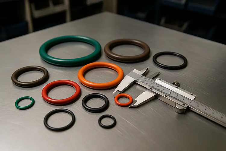
The O-ring is one of the simplest and most widely used sealing elements in pumps.
It is an elastomeric ring with a circular cross-section that provides sealing by deforming and filling the gap between mating surfaces when compressed.
O-rings are favored because they are:
- Cost-effective and easy to manufacture.
- Compact and suitable for both static and dynamic sealing.
- Reliable when installed correctly and made from the right material.
In many pump applications, O-rings are used as secondary seals in mechanical seals or as primary seals in static joints.
3.2 Common Leakage Causes in O-ring Seals
3.2.1 Dimensional and Surface Tolerance Issues
- Groove Dimensions Out of Tolerance
The most critical factor is groove depth—if too deep, the O-ring will not be sufficiently compressed; if too shallow, it will be over-compressed, leading to early wear.
Surface roughness also matters—rough surfaces can cut or abrade the O-ring during installation. - Incorrect O-ring Size
An O-ring that is too small or too large will either stretch excessively or compress improperly, affecting sealing performance.
3.2.2 Manufacturing Defects
- Molding Flash Not Removed: Small leftover material (flash) from the molding process can prevent proper sealing.
- Shape Irregularities: Non-uniform cross-section reduces sealing effectiveness.
3.2.3 Material and Aging Problems
- Incorrect Hardness or Elasticity: The O-ring must be soft enough to deform but hard enough to resist extrusion.
- Material Incompatibility: Using nitrile (NBR) in high-temperature steam service, for example, will cause swelling, cracking, or dissolution.
- Aging and Degradation: Over time, exposure to heat, chemicals, and UV light can cause hardening and loss of elasticity.
3.3 Material Selection Guidelines
Choosing the right O-ring material is essential for long service life:
- Nitrile (NBR): Good oil resistance, general-purpose use.
- Fluoroelastomer (FKM, Viton®): Excellent chemical and temperature resistance.
- EPDM: Resistant to water and steam, but not compatible with oils.
- Silicone: Good flexibility at low temperatures, but lower tear resistance.
- PTFE-encapsulated O-rings: Used in aggressive chemical environments.
3.4 Installation Best Practices
- Ensure groove dimensions match design specifications.
- Lightly lubricate O-rings during installation to prevent twisting or tearing.
- Avoid sharp edges or burrs on mating surfaces—chamfer edges if necessary.
- Replace O-rings during every major maintenance cycle, even if they appear intact, as degradation may not be visible.
3.5 Real-World Example
In a municipal water pumping station, repeated O-ring failures occurred within six months of replacement. Investigation revealed that the O-rings were EPDM, but the pump was handling chlorinated water, which degraded the material. Switching to FKM (Viton®) O-rings resolved the issue, extending service life to over three years.
4. Dynamic Seal / Auxiliary Impeller Seal
4.1 Introduction
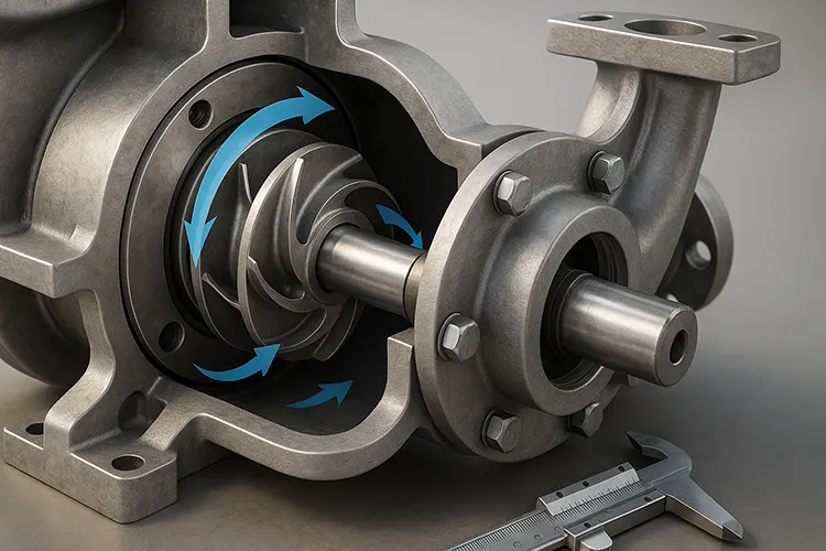
A dynamic seal—in the context of centrifugal pumps—often refers to an auxiliary impeller seal.
Unlike static sealing methods, dynamic seals rely on the motion of the pump components to create a pressure barrier during operation.
In an auxiliary impeller design, a secondary impeller (located behind the main impeller) generates a reverse pressure that counteracts the fluid pressure in the seal chamber, significantly reducing or eliminating leakage when the pump is running.
4.2 How It Works
- During Operation:
The auxiliary impeller rotates with the pump shaft, creating a centrifugal force that pushes the pumped fluid away from the seal area. This establishes a low-pressure zone, preventing leakage past the shaft sleeve. - When Stopped:
The auxiliary impeller loses its sealing effect because centrifugal force is absent. In such cases, a shutdown seal (parking seal) is typically used in combination to prevent leakage when the pump is idle.
4.3 Application Limitations
- Pressure Limitations
The auxiliary impeller can only balance up to a certain design pressure. If inlet or system pressure exceeds this limit, significant leakage will occur. - Dependence on Operating Conditions
Seal effectiveness is strongly tied to pump speed and inlet conditions. For example:- Reduced pump speed lowers sealing performance.
- Changes in suction pressure can disrupt the pressure balance.
- Energy Consumption
The auxiliary impeller consumes some of the pump’s power, slightly reducing overall efficiency.
4.4 Common Failure Causes
- Exceeding Design Pressure: When system or suction pressure rises above the allowable limit.
- Seal Wear: Abrasive particles in the pumped medium can erode sealing surfaces.
- Improper Shutdown Seal: Failure of the shutdown seal during idle periods leads to leakage.
- Inlet Pressure Fluctuations: Sudden changes in suction pressure can momentarily break the pressure barrier.
4.5 Maintenance and Troubleshooting Tips
- Monitor Suction Pressure: Keep inlet pressure within the manufacturer’s specified range.
- Check for Wear: Inspect auxiliary impeller vanes and sealing surfaces for erosion or pitting.
- Maintain Shutdown Seal: Ensure the parking seal is in good condition to prevent idle-time leakage.
- Use Clean Fluid: Where possible, filter the pumped medium to reduce particle ingress that could damage seal surfaces.
4.6 Real-World Example
A paper mill’s vacuum pump using an auxiliary impeller seal experienced leakage during shutdowns. Investigation revealed the shutdown seal had hardened and lost flexibility due to prolonged exposure to hot process water. Replacing it with a high-temperature EPDM seal restored sealing performance and reduced maintenance downtime by 40%.
5. Labyrinth Seal
5.1 Introduction
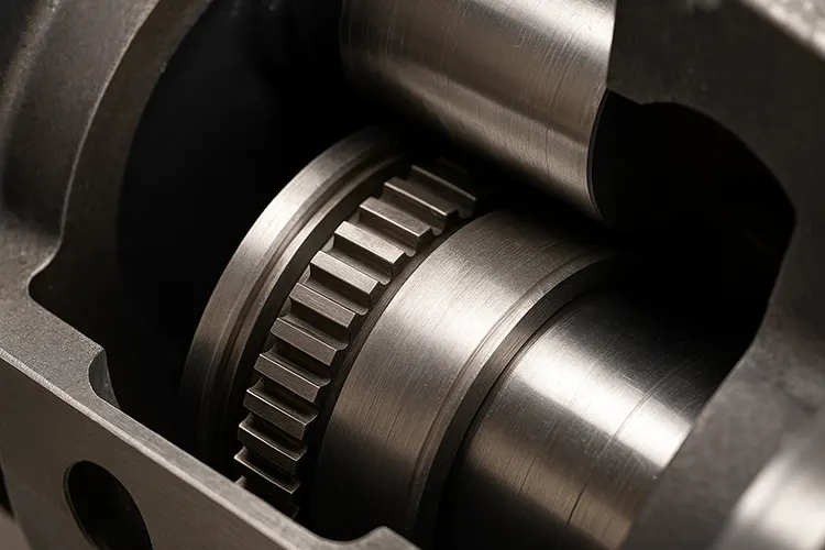
A labyrinth seal is a non-contact sealing method widely used in pumps, turbines, compressors, and other rotating machinery.
Instead of direct contact between sealing surfaces, it uses a series of intricate grooves and ridges to create a tortuous path that makes fluid leakage more difficult.
Because there is no physical contact, labyrinth seals have low friction, long service life, and can operate at high shaft speeds without significant wear.
5.2 How It Works
- The grooved geometry of the labyrinth seal forces any leaking fluid to change direction multiple times.
- Each directional change reduces fluid pressure and slows flow velocity, thereby minimizing leakage.
- In many designs, the small clearances between the rotating and stationary parts are filled with a thin layer of fluid or gas that helps resist further leakage.
5.3 Advantages
- No physical wear: Since the parts do not touch, service life is long.
- High-speed capability: Suitable for high RPM applications.
- Low maintenance: No regular replacement needed if clearances remain within limits.
5.4 Common Leakage Causes
Despite their advantages, labyrinth seals can fail or perform poorly in real-world applications:
5.4.1 Excessive Clearance
- If the gap between the rotating shaft and the seal housing becomes too large, sealing effectiveness decreases significantly.
- Cause: Poor machining, improper assembly, or wear over time.
5.4.2 Surface Roughness Issues
- Spiral tool marks or poor finish on the sealing surfaces can actually promote leakage by creating a directional flow path.
5.4.3 Lubrication Oil Overflow
- In pump bearing housings, excess oil can build up pressure higher than the seal’s capability, forcing fluid past the labyrinth.
5.4.4 Incorrect Oil Level Indication
- Misplaced sight glasses or level gauges can cause overfilling, leading to oil leakage.
5.4.5 Temperature Effects
- Rising oil temperature reduces viscosity, making it easier for the fluid to leak through the clearances.
5.4.6 Blocked Return Passages
- If return grooves or drain holes are too small or clogged, trapped oil cannot flow back to the sump, increasing leakage risk.
5.5 Maintenance and Design Recommendations
- Precision Machining: Maintain tight tolerances and correct concentricity during manufacturing.
- Surface Finish Control: Avoid spiral machining marks and ensure smooth sealing surfaces.
- Oil Level Monitoring: Use accurately positioned sight glasses to prevent overfilling.
- Temperature Control: Ensure proper cooling to keep lubricant viscosity within optimal range.
- Clear Drain Paths: Keep return grooves and holes unobstructed for efficient oil return.
5.6 Real-World Example
In a large centrifugal pump used in a refinery, frequent bearing oil leaks occurred despite using a labyrinth seal. Investigation found that the bearing housing oil return holes were partially blocked by solidified lubricant. Cleaning the passages and slightly increasing their diameter eliminated leakage, extending the maintenance interval from six months to over two years.
6. Thread Seal
6.1 Introduction
A thread seal is one of the most reliable and long-lasting sealing methods for certain pump components and piping connections.
It relies on the mating of male and female screw threads to create a tight mechanical fit, often enhanced by a sealing compound or tape.
Thread seals are commonly used in:
- Auxiliary piping connections in pump systems.
- Process ports and maintenance openings.
- Blind or standby ports that require temporary or long-term closure.
When properly machined, assembled, and sealed, threaded connections can withstand high pressures and long service intervals with minimal maintenance.
6.2 How It Works
The sealing action of a threaded connection is achieved through:
- Metal-to-metal contact between the thread flanks, which reduces clearance and limits leakage paths.
- Deformation of the sealing material (such as PTFE tape or liquid sealant) that fills microscopic gaps between threads.
- Tapered thread designs that tighten progressively, increasing radial pressure as the connection is made.
6.3 Common Leakage Causes
6.3.1 Dimensional Inaccuracies
- Oversized Thread Tapping: If the drilled hole for the female thread is too large, the resulting thread depth is too shallow, reducing the contact area and sealing effectiveness.
- Undersized Male Thread Diameter: Leads to a loose fit, lowering the sealing pressure.
- Tool Wear or Incorrect Grinding: Even if standard drill sizes are used, incorrectly sharpened bits can cause dimensional deviations.
6.3.2 Insufficient or Incompatible Sealant
- Some thread seal designs, especially tapered threads, require an additional sealing medium.
- Using too little sealant or one that is chemically incompatible with the pumped fluid can result in corrosion, dissolution, and leakage.
- This is common in petrochemical applications where aggressive fluids quickly degrade unsuitable sealants.
6.4 Best Practices for Reliable Thread Sealing
- Precision Machining
- Use correctly sharpened tools and maintain equipment calibration.
- Follow standard thread depth and diameter specifications.
- Choose the Right Sealant
- PTFE tape: Good for general water, oil, and gas service.
- Anaerobic liquid sealants: Excellent for permanent, vibration-resistant seals.
- High-temperature compounds: Required for steam or high-heat applications.
- Apply Sealant Properly
- For PTFE tape: Wrap in the direction of thread engagement to avoid unraveling during assembly.
- For liquid sealants: Ensure threads are clean and oil-free before application.
- Avoid Over-Tightening
- Excessive torque can strip threads, distort sealing surfaces, or damage components.
6.5 Real-World Example
A chemical transfer pump in a fertilizer plant experienced recurrent leakage from a pressure gauge connection. The root cause was found to be a mismatch between the thread type (BSPT male fitting into an NPT female port) and the absence of a suitable sealant. After switching to matching threads and applying a high-performance anaerobic sealant, the joint remained leak-free for over three years of continuous operation.
7. Conclusion: The Importance of Optimizing Pump Sealing
7.1 Summary of Key Points
Pump sealing is not a secondary design detail—it is a critical factor in ensuring operational reliability, environmental compliance, and cost efficiency.
From mechanical seals to O-rings, dynamic seals, labyrinth seals, and thread seals, each method has its own advantages, limitations, and specific application requirements.
Key takeaways from this guide:
- Mechanical Seals offer high performance for demanding applications but require precise installation, correct material selection, and proper flushing systems.
- O-rings are cost-effective and versatile but highly dependent on correct groove design, material compatibility, and installation practices.
- Dynamic Seals (Auxiliary Impeller) can eliminate leakage during operation but are limited by design pressure and require a shutdown seal for idle periods.
- Labyrinth Seals excel in high-speed, low-maintenance scenarios but depend heavily on precise clearances and clean return paths.
- Thread Seals provide long-lasting, leak-free joints when machining accuracy and sealant selection are correct.
7.2 Why Seal Optimization Matters
In today’s industrial environment, energy efficiency, safety, and environmental regulations are stricter than ever.
Pump leakage can result in:
- Product loss → increased production costs.
- Safety risks → hazardous fluid exposure to workers.
- Environmental fines → due to spills or emissions.
- Unplanned downtime → disrupting operations and delaying projects.
By implementing proper seal selection, installation, and maintenance practices, companies can:
- Extend equipment life.
- Reduce total cost of ownership (TCO).
- Improve workplace safety and compliance.
- Enhance operational efficiency.
7.3 Best Practices for Long-Term Sealing Success
- Understand the Application: Fluid type, temperature, pressure, and shaft speed all determine the best seal type.
- Prioritize Material Compatibility: Ensure seal materials resist chemical attack, swelling, or thermal degradation.
- Control Installation Quality: Even the best seal can fail prematurely if installed incorrectly.
- Implement Preventive Maintenance: Regular inspections, lubrication checks, and replacement schedules prevent unexpected failures.
- Train Maintenance Personnel: Proper handling and installation techniques greatly reduce seal-related downtime.
7.4 Looking Forward
With the increasing demand for energy-saving and environmentally friendly industrial equipment, the role of advanced sealing technologies will become even more important.
Developments such as non-contact seals with active pressure balancing, smart seals with leakage detection sensors, and eco-friendly seal materials will shape the next generation of pump sealing solutions.
Related Articles
Static vs Dynamic Seals: Guide to Reliable Sealing
Explore the differences between static and dynamic seals, including design tips, material considerations, and application scenarios.
Common Seal Leakage Problems and Effective Solutions
Learn about frequent sealing failures in pumps and other equipment, along with proven troubleshooting and prevention strategies.
Types of Rubber Seals by Shape, Material, and Use
Understand various rubber seal types, their material properties, and how to select the right seal for specific industrial applications.